
Sensor component housing

一种传感器、构件的技术,应用在传感器构件壳体领域,能够解决传感器难接近、昂贵、损失等问题,达到避免不密封的效果

Inactive Publication Date: 2014-01-29
SCHOTT AG
View PDF10 Cites 6 Cited by
  • Summary
  • Abstract
  • Description
  • Claims
  • Application Information

AI Technical Summary

Problems solved by technology

In such cases, expensive special sensors have to be used for the so-called media-side arrangement of the sensors on the feedthrough
[0005] A further disadvantage of sensors arranged on the medium side is that in the event of a fault a sensor arranged in the above manner is very inaccessible or even inaccessible
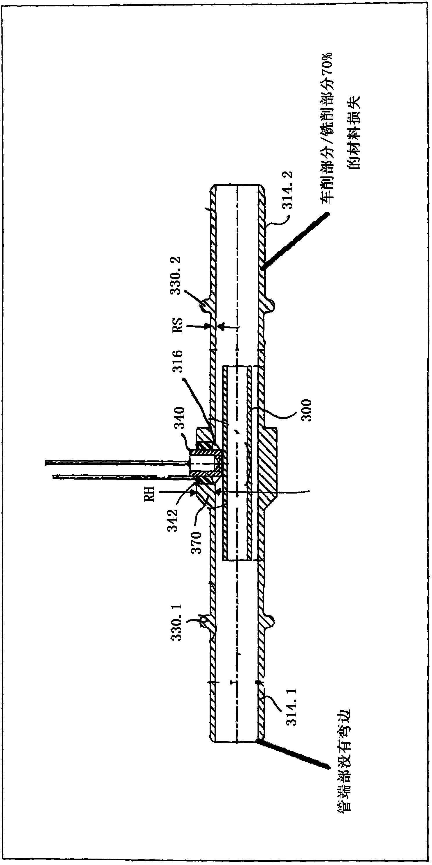
However, the production of the sensor component housing according to US 2010 / 0186501 A1 by means of turning and milling processes is very complex
In addition, a high material loss of up to 75% occurs from the blank to the finished part

Method used


Image

  • Sensor component housing
  • Sensor component housing
  • Sensor component housing

Examples


Embodiment Construction

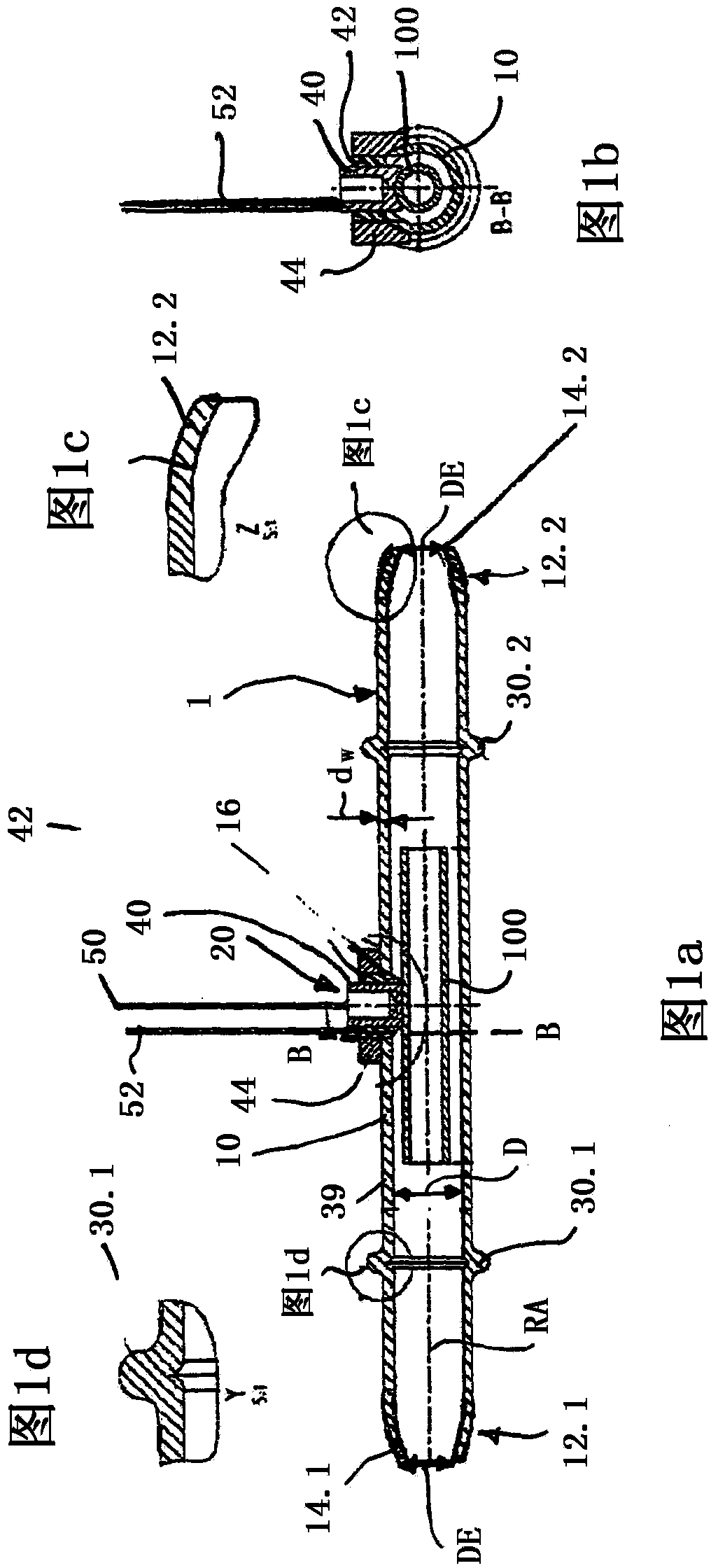
[0042] exist Figures 1a to 1d shows a device for receiving and / or conducting a liquid or gaseous medium with a sensor component 100 which is inserted into a sensor component housing 10 according to the invention. Figure 1a A longitudinal section through a device 1 of this type is shown. The sensor component housing 10 has a circular cross-section, which in Figure 1b is shown in the plane B-B.

[0043] The circular tube cross-section has a diameter D. According to the invention it is provided that the sensor component housing 10 has a bead 14.1 or 14.2 in the region of the first end 12.1 and the second end 12.2. Flange 12.2 in Figure 1c shown in detail. During flanging, the first end 12.1 or the second end 12.2 of the tube section of the sensor component housing 10 is upset, for example with a forming tool, the diameter is reduced from the diameter D in the region of the tube center to the tube end. Diameter DE at section (12.1, 12.2). Although the diameter DE at the...


PUM


Abstract

The invention relates to a sensor component housing (10) comprising at least one tube section with a tube wall (39), wherein the tube wall has an opening (16) and the tube section has a diameter (D) and a first and a second end (12.1, 12.2). It is characterized in that the first and / or the second end has tilted areas (14.1, 14.2) such that the diameter tapers to an end diameter (DE) toward the first and / or second end of the tube section.

Description

technical field [0001] The invention relates to a sensor component housing comprising a tube section with a tube wall, wherein the tube wall has an opening and the tube section has a diameter and a first end and a second end, and The invention relates to a method for producing a sensor component housing and a device with a sensor component housing for receiving and / or conducting a liquid or gaseous medium. Background technique [0002] Various types of sensors, such as temperature sensors, are used in the prior art in order to detect physical properties of a medium, such as a liquid or a gas. The medium whose physical properties (eg temperature) are to be sensed is, for example, guided in a piping system or stored in a container, eg an oil tank. [0003] Up to now, sensors for fast detection of physical quantities (eg temperature) have been located on the side of the feedthrough close to the medium, that is to say close to the liquid or gas. [0004] Sensors arranged in th...

Claims


Application Information

Patent Timeline
Patent Type & Authority Applications(China)
IPC IPC(8): G01N27/22G01N27/07G01K1/14G01K13/02
CPCG01K2205/04G01N33/28G01K13/02G01N27/226G01N27/07Y10T29/49826G01D11/245
Inventor 莱茵哈德·兰夫特尔赫尔穆特·哈特尔
Owner SCHOTT AG
Learn More