Novel vacuum suction plate structure

A vacuum suction plate and vacuum suction cup technology, applied in suction cups, connecting components, mechanical equipment, etc., can solve the problems of economic loss, application obstruction, unstable performance, etc., and achieve the effects of preventing unsealing, enhancing strength, and stable performance.

Active Publication Date: 2020-01-31
福州派可吉贸易有限公司
View PDF8 Cites 1 Cited by
  • Summary
  • Abstract
  • Description
  • Claims
  • Application Information

AI Technical Summary

Problems solved by technology

[0002] The vacuum suction plate is used in the cargo handling industry, which puts great demands on the stable performance of the vacuum suction plate. Once the performance is unstable, it will face huge economic losses
At present, the performance of vacuum suction plates on the market is relatively unstable, which hinders its application and is not conducive to promotion

Method used


Image

  • Novel vacuum suction plate structure
  • Novel vacuum suction plate structure
  • Novel vacuum suction plate structure

Examples


Embodiment 1

[0043] Please refer to Figure 1-7 Shown, embodiment one of the present invention is:

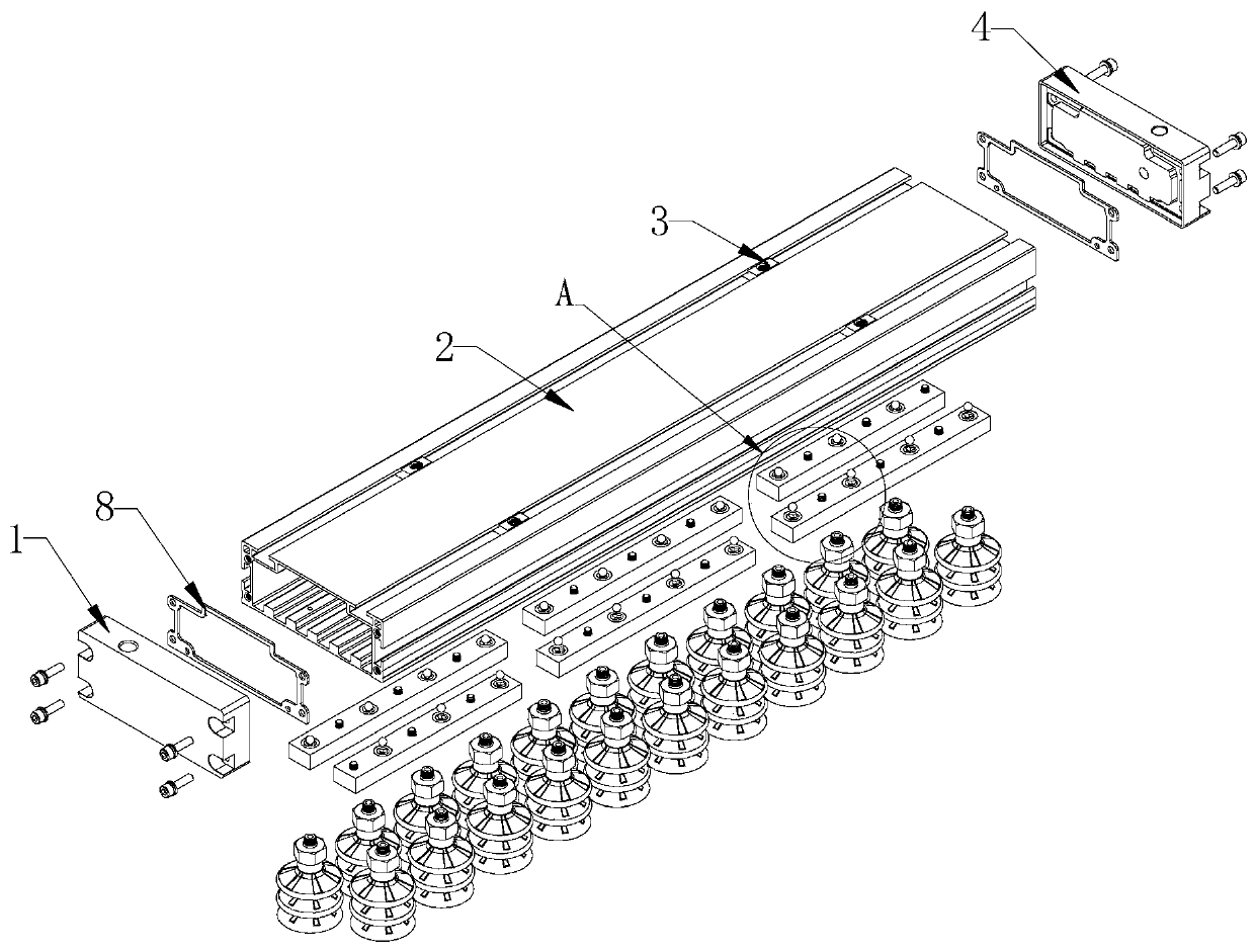
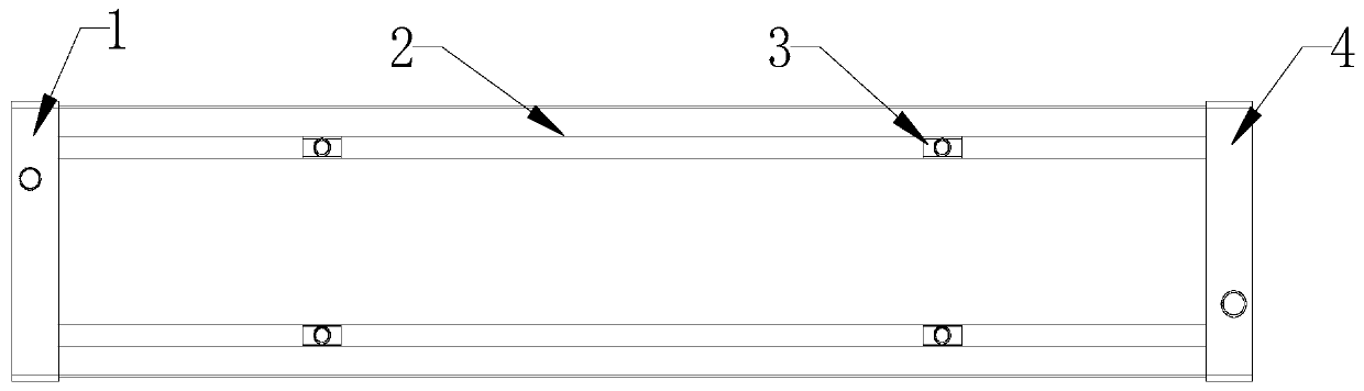
[0044] A novel vacuum suction plate structure of the present invention includes a suction plate and a suction cup assembly;

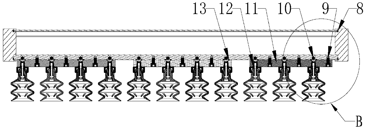
[0045] The suction plate includes a left side cover 1, a suction plate main body 2, a nut block 3, a right side cover 4, a side cover gasket 8, a screw 9, a stainless steel bead 10, a suction cup bead 11 and a sealing ring 13; the suction plate main body 2 is a shell with openings at opposite ends and a hollow interior, the shell is in the shape of a strip-shaped cuboid, and is integrally formed of metal material. The left side cover 1 and the right side cover 4 are respectively arranged at the openings at both ends of the suction plate main body 2, the side of the left side cover 1 close to the suction plate main body and the right side cover 4 close to the suction plate main body are both A groove matching the end of the main body of the suction plate is provided...


PUM


Abstract

The invention relates to the technical field of mechanical structures, and particularly relates to a novel vacuum suction plate structure. A suction plate body, a left side cover and a right side cover are designed in an embedded mode; a side cover sealing gasket is embedded into a sealing gasket positioning groove in the bottom face of the groove firstly, and then the suction plate body is embedded into a side cover groove and fastened to the suction plate body through fixing screws on the end faces of the side cover. The positions of stainless steel balls in stepped holes are adjusted in a self-adaptive mode according to the vacuum suction force, and a suction cup assembly is in threaded connection with internal threads of through holes of suction cup pressing strips through external threads of suction cup fixing nuts and is sealed through an annular sealing ring; a filter screen is arranged between the suction cup fixing nuts and a throttling valve and positioned on an air channel of the suction cup fixing nuts and the throttling valve, and the effects of filtering air and preventing dust impurities in air from being sucked into a suction plate through the air channel and affecting vacuum control elements after blockage to cause damage and action failure are achieved.

Description

technical field [0001] The invention relates to the technical field of mechanical structures, in particular to a novel vacuum suction plate structure. Background technique [0002] The vacuum suction plate is used in the cargo handling industry, which puts great demands on the stable performance of the vacuum suction plate. Once the performance is unstable, it will face huge economic losses. At present, the performance of vacuum suction plates on the market is relatively unstable, which hinders its application and is not conducive to promotion. Contents of the invention [0003] In order to overcome the above-mentioned defects of the prior art, the technical problem to be solved by the present invention is to provide a novel vacuum suction plate structure, which has a simple structure and relatively stable performance. [0004] In order to solve the problems of the technologies described above, the technical solution adopted in the present invention is: [0005] New vacu...

Claims


Application Information

Patent Timeline
Patent Type & Authority Applications(China)
IPC IPC(8): B65G47/91F16B47/00
CPCB65G47/918F16B47/00
Inventor 骆景波谢光瑞林光华
Owner 福州派可吉贸易有限公司
Why Eureka
Try Eureka