
Fuel rod storage device

A technology for fuel rod storage and fuel rods, which is applied in the direction of reactor fuel elements, reactors, and reduction of greenhouse gases. It can solve problems such as weld damage and achieve high functional reliability and low maintenance requirements.

Active Publication Date: 2016-02-24
GNS核能服务有限公司
View PDF6 Cites 1 Cited by
  • Summary
  • Abstract
  • Description
  • Claims
  • Application Information

AI Technical Summary

Problems solved by technology

When the fuel rod storage is subjected to high mechanical loads or when the length of the receiving tube changes due to heat, the weld seam is heavily loaded, so that the weld seam can be damaged

Method used


Image

  • Fuel rod storage device
  • Fuel rod storage device
  • Fuel rod storage device

Examples


Embodiment Construction

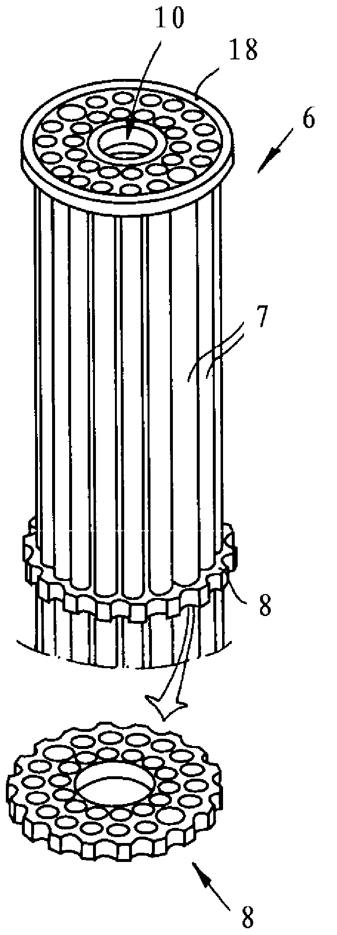
[0033] exist figure 1 A fuel rod storage 1 is shown in , which has a storage bottom 2 , a storage shell 3 and a storage cover 4 . Preferably and according to the described exemplary embodiment, the fuel rod store 1 is designed as a cuboid. The storage shell 3 has webs S which, according to the described exemplary embodiment, serve as support surfaces when storing and / or transporting the fuel rod storage. according to figure 1 , Install the buffer 5a on the reservoir cover 4. A buffer 5b is mounted on the bottom side or towards the container bottom 2, so that preferably and according to the described embodiment the length of the fuel rod container 1 including the buffers 5a, 5b is equal to the length of the fuel elements.

[0034] exist figure 1 Not shown, the support surface of the storage bottom side of the buffer 5b has drainage grooves through which water can be conducted when the buffer-protected fuel rod storage 1 is removed from the storage tank.

[0035] In Fig. 2a...


PUM


Abstract

The present invention relates to a fuel rod storage device, particularly to a fuel rod storage device for fuel rods, preferably damaged fuel rods. The fuel rod storage device forms an integrated, preferably forged fuel rod storage device, and is provided with an inner cavity enclosed by a storage device bottom, a storage device housing and a storage device cover, wherein the storage device cover is provided with a storage device cover opening capable of being sealed by a sealed member, at least an accommodation pipe for the fuel rod is arranged inside the inner cavity, and is sealed on the end portion of the storage device bottom side in a fluid sealing manner, and the sealed member can be loaded, preferably screwed into the storage device opening.

Description

technical field [0001] The invention relates to a fuel rod storage, in particular a fuel rod storage for fuel rods, preferably for damaged fuel rods. Background technique [0002] It is known in principle to pack spent fuel elements into mechanically high-load containers for storage and / or transport. Such shipping containers and / or storage containers bear the trade name or A known. During the operation of a nuclear power plant, damage to fuel elements may occur. Since it is not possible to clearly assess the mechanical properties of especially damaged fuel elements, it is important to pack damaged fuel elements into transport containers and / or storage containers. Damaged fuel elements are stored in decay pools after removal from the reactor, wherein during storage water can get into the fuel elements or into the casing surrounding the nuclear fuel. Since water can escape from damaged fuel elements when storing such damaged fuel elements in the storage and / or transport...

Claims


Application Information

Patent Timeline
Patent Type & Authority Applications(China)
IPC IPC(8): G21C19/06
CPCY02E30/30
Inventor A·班纳尼W·策布拉R·许根伯格H·屈尔
Owner GNS核能服务有限公司
Learn More