Knee joint correction device

A knee joint and ankle joint technology, applied in the field of knee joint correction devices, can solve the problems of narrow knee joint space, dependence, and increased incidence of knee joints, and achieve the effect of reducing extra load and enhancing stability

Active Publication Date: 2014-02-05
SHANGHAI WANBANG MEDICAL EQUIP TECH +1
View PDF8 Cites 4 Cited by
  • Summary
  • Abstract
  • Description
  • Claims
  • Application Information

AI Technical Summary

Problems solved by technology

[0002] At present, the incidence of diseases caused by the deformation of the knee joint is on the rise, such as: narrow knee joint space, acute and chronic injury or displacement of the meniscus, pain caused by wrong force points on the upper and lower contact surfaces of the knee joint, tibial tuberosity or femur The displacement of the flat fracture of the trochanter and the acute and chronic strain of the ligaments and tendons around the knee joint, valgus or varus of the knee joint, resulting in O-shaped or X-shaped legs, and chronic pain. When the disease is severe, the patient will not be able to walk. Work brings a lot of inconvenience
[0003] If you rely on drugs to treat the above diseases, the curative effect is generally slow and the recovery time is long; if you rely on surgery, the effect depends on the doctor's experience, and it is usually expensive, and adverse effects such as postoperative infection may also occur
In addition, most of the existing knee joint correction devices focus on solving the problem of how to restore the knee joint to its bent state, but the above-mentioned knee joint deformation cannot be improved by such correction methods. Symptom relief is very limited

Method used


Image

  • Knee joint correction device
  • Knee joint correction device
  • Knee joint correction device

Examples


Embodiment Construction

[0059] Preferred embodiments of the present invention are described below in conjunction with several drawings.

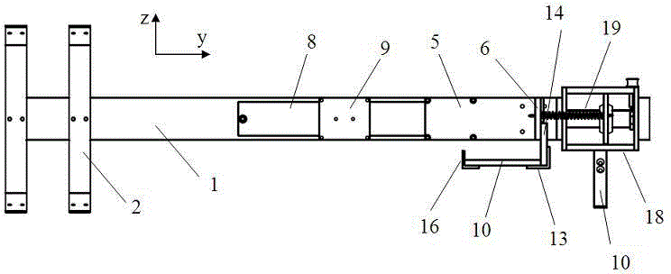
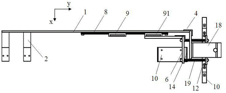
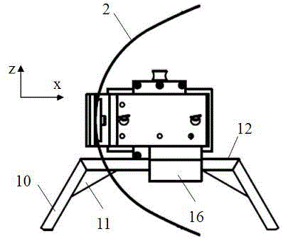
[0060] Cooperate see Figure 1a , Figure 1b , Figure 1c , Figure 1d , Figure 1e As shown, the three planes of the knee joint correction device of the present invention are set as: the first plane (ie the yoz plane), the second plane (ie the xoy plane), and the third plane (ie the xoz plane), wherein the second plane is Horizontal planes, the first plane and the third plane are perpendicular to each other and are respectively perpendicular to the second plane. The "front end" and "rear end" described in this article correspond to the up and down positions of the human body when standing. Figure 1a , Figure 1b Correspondence in the middle is expressed as the left and right ends.

[0061] Described orthodontic device comprises and is located at the fixing plate 1 of first side (see figure 2 ). One side of the front end of the fixed plate 1 is provided wi...


PUM


Abstract

The invention provides a knee joint correction device. A fixing plate is arranged on the inner side or the outer side of one leg of a patient; fixing plate battens are used for fixing the part at the upper part of the knee joint; a pulling bottom plate is connected with the rear end of the inner side of the fixing plate; a guide rail is arranged in the length direction of the fixing plate; a heel supporting and stretching mechanism moves along the guide rail through a first sliding block to guide the part at the lower part of an ankle joint of the patient to move towards the direction far away from the knee joint of the patient, so as to enable the gaps formed in the knee joint of the patient to be widened; a first fixing band is used for fixing the ankle joint part; a second fixing band on a second sliding block is used for fixing the part at the lower part of the knee joint of the patient, and is tightly banded during traction to apply acting force capable of twisting the knee joint and enabling the knee joint to be close and attached to the fixing plate to the knee joint of the patient. According to the invention, the gaps formed in the knee joint are widened through traction, and the fixing bands below the knee are internally and tightly banded under traction to enable a thigh, the knee and the ankle to form a certain physiological line, so that the shape in the pathological state is corrected.

Description

technical field [0001] The invention relates to a medical device, in particular to a knee joint correction device. Background technique [0002] At present, the incidence of diseases caused by deformation of the knee joint is on the rise, such as: narrow knee joint space, acute and chronic injury or displacement of the meniscus, pain caused by wrong force points on the upper and lower contact surfaces of the knee joint, tibial tuberosity or femur The displacement of the flat fracture of the trochanter and the acute and chronic strain of the ligaments and tendons around the knee joint, valgus or varus of the knee joint, resulting in O-shaped or X-shaped legs, and chronic pain. When the disease is severe, the patient will not be able to walk. Work brings a lot of inconvenience. [0003] If you rely on drugs to treat the above diseases, the curative effect is generally slow and the recovery time is long; if you rely on surgery, the effect depends on the doctor's experience, an...

Claims


Application Information

Patent Timeline
Patent Type & Authority Applications(China)
IPC IPC(8): A61F5/048
Inventor 黄声
Owner SHANGHAI WANBANG MEDICAL EQUIP TECH
Why Eureka
Try Eureka