
Motor vehicle emergency alarming and brake stopping device

An emergency alarm and parking device technology, applied in the direction of automatic starting devices, motor vehicles, signal devices, etc., can solve problems such as blind spots, vehicles that cannot be seen or are about to drive, brake pad traffic accidents, etc.

Active Publication Date: 2014-02-05
BOYE COUNTY SHUNYI NEW ENERGY AUTOMOBILE TECH CO LTD
View PDF7 Cites 5 Cited by
  • Summary
  • Abstract
  • Description
  • Claims
  • Application Information

AI Technical Summary

Problems solved by technology

Also, when the vehicle is going downhill on the mountain road, the failure of the brake pads due to overheating often leads to traffic accidents. For this reason, sand pits must be prepared on the side of the long and steep mountain road, so that the vehicle with brake failure will be in the sand pit. stop the car in order to prevent bigger traffic accidents; but these are not the root of the problem
Existing motor vehicles observe the situation of the front, rear, front left and front right of the vehicle by human eyes and multiple rearview mirrors. What cannot be observed has a blind spot, so traffic accidents often occur, such as reversing and hitting an obstacle, someone in front, especially a child, knocked down because they cannot see the vehicle that is driving or is about to drive, and when the vehicle is driving in the opposite direction due to the amount of traffic. , traffic accidents where two vehicles collide, etc.; for this reason, people have installed a reversing radar, but it is only an alarm for reversing when it is too close to an obstacle, and it must be controlled by a person to stop the reversing. Dangerous situation, when people's thinking is confused, it is impossible to stop the vehicle from running
And there is still no way to the front, front left and front right

Method used


Image

  • Motor vehicle emergency alarming and brake stopping device

Examples


Embodiment Construction

[0010] The present invention will be further described below in conjunction with the accompanying drawings and specific embodiments.

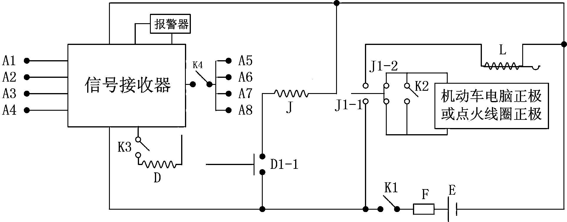
[0011] like figure 1 As shown, this embodiment includes four infrared sensors A1, A2, A3, A4, A5, A6, A7, A8, signal receivers, contactors, relays, alarms, and DC power supplies E respectively installed at the front and rear ends of the vehicle. and switches K1, K2, K3 and K4. The signal output ends of the infrared sensors A1, A2, A3, A4 are connected to the signal input ends of the signal receiver, the signal output ends of the infrared sensors A5, A6, A7, A8 are connected to the signal input ends of the signal receiver through the switch K4, and the infrared sensor's The signal output end is connected to the signal input end of the signal receiver, and the signal output end of the signal receiver is connected to both ends of the coil of the contactor D through the switch K3, and the normally open contact D1-1 end of the contactor D is passed...


PUM


Abstract

The invention discloses a motor vehicle emergency alarming and brake stopping device. A signal output end of a sensor is connected with a signal input end of a signal receiver, a signal output end of the signal receiver is connected to two ends of a coil of a contactor D through a switch K3, one end of a normally-open contact D1-1 of the contactor D is connected to the positive electrode of a direct current power source E through a power source switch K1, the other end of the normally-open contact D1-1 of the contactor D is connected to one end of a coil of a relay J, and the other end of the coil of the relay J is connected to the negative electrode of the direct current power source E. One end of a normally-open contact J1-1 of the relay J is connected to the positive electrode of the direct current power source E, and the other end of the normally-open contact J1-1 of the relay J is connected to one end of an electromagnet coil L on a vehicle brake. Two ends of a normally-closed contact J1-1 of the relay J are parallelly connected with a switch K2 and then connected to the positive electrode of a motor vehicle computer or the positive electrode of an ignition coil. By arranging the motor vehicle emergency alarming and brake stopping device on a motor vehicle, when the distance between barriers and vehicle is within the sensing range of the sensor, the vehicle can automatically perform emergency brake or flame out timely to avoid traffic accidents.

Description

technical field [0001] The invention relates to an emergency alarm and brake parking device for a motor vehicle. Background technique [0002] When people are driving tired, they will fall asleep while driving, and it is very dangerous to collide with other vehicles. Therefore, fatigue driving is strictly prohibited, but there are still many violations, and traffic accidents caused by fatigue driving continue to occur. , especially on highways and national roads. Also, when the vehicle is going downhill on the mountain road, the failure of the brake pads due to overheating often leads to traffic accidents. For this reason, sand pits must be prepared on the side of the long and steep mountain road, so that the vehicle with brake failure will be in the sand pit. Stop the car in order to prevent larger traffic accidents; but these are not the root of the problem. Existing motor vehicles observe the situation of the front, rear, front left and front right of the vehicle by hum...

Claims


Application Information

Patent Timeline
IPC IPC(8): B60T7/12B60Q9/00B60K28/14
Inventor 郝占秋
Owner BOYE COUNTY SHUNYI NEW ENERGY AUTOMOBILE TECH CO LTD
Learn More