Self-locking rail clamping device

A technology of self-locking clips and clamping pliers, applied in the directions of traveling mechanism, load hanging element, transportation and packaging, etc., can solve problems such as track disengagement, and achieve the effect of simple structure and easy manufacturing.

Inactive Publication Date: 2014-02-05
HUZHOU YANGXI ELEVATORING EQUIP
View PDF7 Cites 9 Cited by
  • Summary
  • Abstract
  • Description
  • Claims
  • Application Information

AI Technical Summary

Problems solved by technology

However, it also has shortcomings, and it will also be disengaged from the track in the event of an accidental power failure.

Method used


Image

  • Self-locking rail clamping device

Examples


Embodiment Construction

[0014] The following descriptions are only preferred embodiments of the present invention, and do not limit the scope of the present invention.

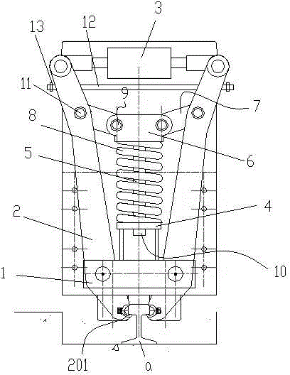
[0015] Examples, see attached figure 1 , a self-locking rail clamp, including a base 1, a pair of clamping pliers 2 with clamping heads 201 hinged on the base 1 and a telescopic device 3 that drives the pair of clamping clamps 2 to rotate, and the clamping clamps 201 are set There are arc-shaped jaws, and the telescopic device drives a pair of clamping pliers 2 to rotate synchronously to realize the clamping or loosening of the chuck 201 on the I-beam guide rail a. The telescopic device 3 is an air cylinder or oil cylinder, a cylinder body and a piston The rods are respectively hinged by two clamping pliers, the base 1 is fixed with a guide sleeve 4, the guide sleeve 4 is provided with a guide rod 5, the upper end of the guide rod 5 is fixed with a blocking ring 6, and the lower end is provided with a tightening ring. fixed nut 10, ...


PUM


Abstract

The invention discloses a self-locking rail clamping device. The self-locking rail clamping device comprises a base, a pair of clamping pliers and a telescopic device, wherein the pair of clamping pliers is hinged to the base and is provided with a clamping chuck, and the telescopic device drives the pair of clamping pliers to rotate; a guiding sleeve is fixed on the base, a guiding rod is arranged in the guiding sleeve, a blocking ring is fixed at the upper end part of the guiding rod, a fastening nut is arranged at the lower end part of the guiding rod, the blocking ring is hinged to the clamping pliers through a pair of link rods, and a compression spring which is located between the blocking ring and the guiding sleeve is sleeved on the guiding rod. The self-locking rail clamping device is simple in structure and easy in production and can guarantee that the rail clamping device is firmly clamped on a rail and can not be disengaged under unexpected conditions, such as power outage and the like.

Description

technical field [0001] The invention relates to the technical field of hoisting equipment, in particular to a self-locking rail clamp. Background technique [0002] The patent announcement number is CN202575729U, and the announcement date: 2012-12-05 Chinese utility model patent discloses the jaw iron for the self-locking rail clamp and the rail clamp. The jaw iron for the rail clamp includes the clamp arm, and the clamp arm A clamping head is fixedly connected, and the clamping head is provided with a clamping part. The clamping part is provided with an opening for accommodating the clamping object. The upper pliers head and the lower pliers head, the openings are respectively connected with the upper pliers head and the lower pliers head. In the utility model, the opening provided on the chuck is used to accommodate the track entity, and the upper and lower jaws are engaged with the track through the power transmitted by the clamp arm, so it is difficult for the track to ...

Claims


Application Information

Patent Timeline
IPC IPC(8): B66C9/18
Inventor 朱晓翔
Owner HUZHOU YANGXI ELEVATORING EQUIP
Why Eureka
Try Eureka