Main girder structure of cable-stayed bridge of large-span railway

A cable-stayed bridge and long-span technology, applied in the direction of cable-stayed bridges, bridges, bridge parts, etc., to achieve the effect of saving steel consumption, large bridge deck width, and improving the wind speed threshold of train operation

Active Publication Date: 2014-02-05
CHINA RAILWAY SIYUAN SURVEY & DESIGN GRP
View PDF6 Cites 11 Cited by
  • Summary
  • Abstract
  • Description
  • Claims
  • Application Information

AI Technical Summary

Problems solved by technology

[0005] Aiming at a series of problems faced by existing steel truss girders and traditional steel box girders in the application of super-long-span (500-900 m) railway cable-stayed bridges, the present invention proposes a steel truss girder that not only has relatively large lateral stiffness, but also can Main girder structure of long-span railway cable-stayed bridges with better wind resistance, improved material utilization and reduced engineering cost

Method used


Image

  • Main girder structure of cable-stayed bridge of large-span railway
  • Main girder structure of cable-stayed bridge of large-span railway

Examples


Embodiment Construction

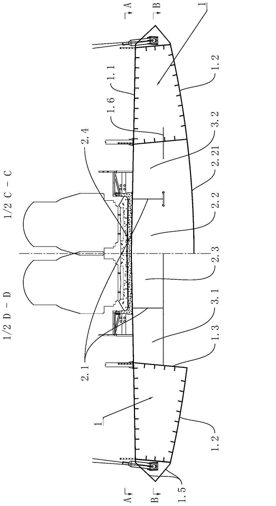
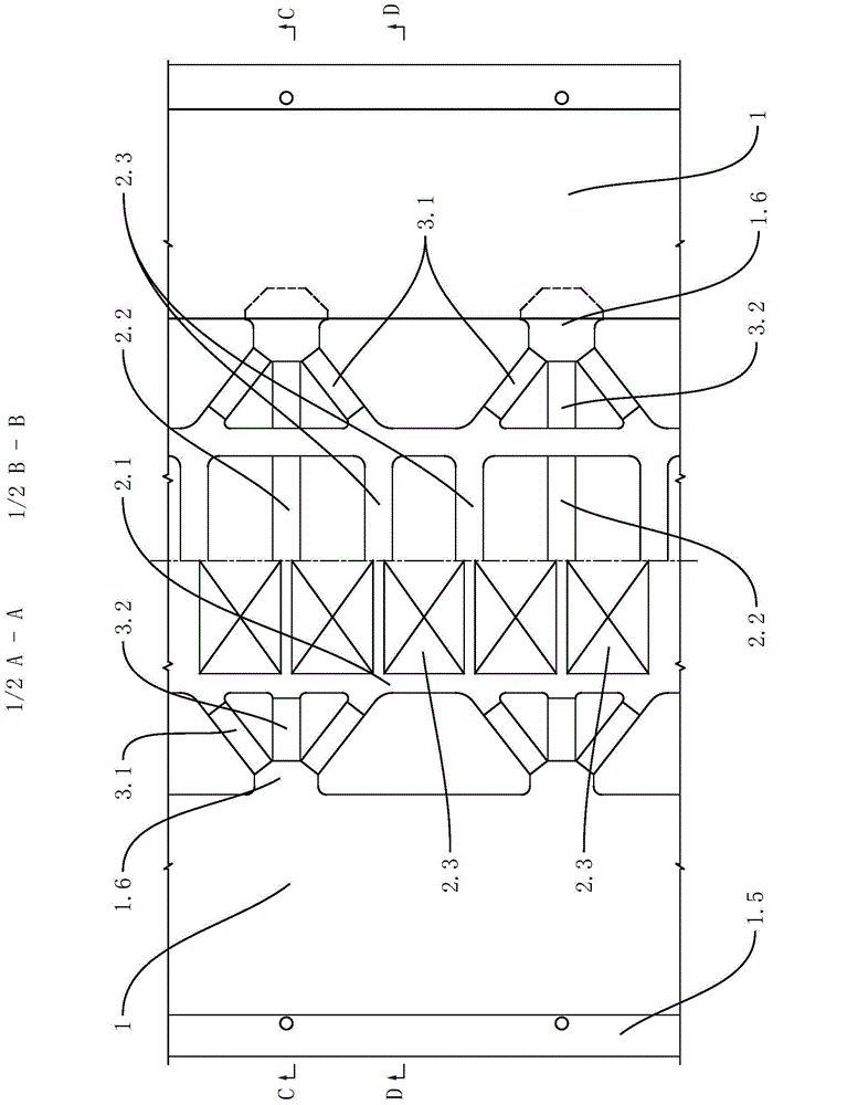
[0014] Such as figure 1 and figure 2 As shown, the main girder structure of a long-span cable-stayed bridge has steel box side girders 1 on both sides, and a longitudinal and horizontal beam deck system 2 in the middle. Side connection; the steel box side beam 1 includes a top plate 1.1 and a bottom plate 1.2, an inner web 1.3 and an outer web 1.4 are arranged between the top plate 1.1 and the bottom plate 1.2, and an air nozzle 1.5 is arranged on the outer web 1.4; The inner web 1.3 is provided with a connection plate 1.6, and a part of the connection plate 1.6 is embedded in the steel box side girder 1, which is convenient for connection and installation with other components; the longitudinal and horizontal beam deck system 2 includes cross-connected Longitudinal beams 2.1 and crossbeams 2.2, transverse ribs 2.3 cross-connected with the longitudinal beams 2.1 are also arranged between the crossbeams 2.2, the top of the longitudinal and transverse beam deck systems 2 is a ...


PUM


Abstract

The invention discloses a main girder structure of a cable-stayed bridge of a large-span railway. The main girder structure comprises steel box boundary beams, a longitudinal and cross beam bridge decking, and horizontal K-shaped supports, wherein the steel box boundary beams are positioned on two sides of a cross section; the longitudinal and cross beam bridge decking is positioned in the middle of the cross section, and comprises longitudinal beams and cross beams; the longitudinal beams and the cross beams are connected in a crossed manner; cross ribs which are connected with the longitudinal beams in the crossed manner are arranged between the cross beams; a concrete bridge deck is arranged at the top of the longitudinal and cross beam bridge decking; the longitudinal and cross beam bridge decking is connected with the side parts of the steel box boundary beams through the K-shaped supports. According to the invention, the main girder of the cable-stayed bridge is divided into three parts of the steel box boundary beams, the longitudinal and cross beam bridge decking, and the horizontal K-shaped supports; compared with a traditional steel box beam, the main girder structure can provide a relatively wide bridge deck width; meanwhile, the steel box boundary beams are distributed on the two sides of the cross section so as to greatly improve the transverse stiffness of the bridge, so that the technical problem of small transverse stiffness of the cable-stayed bridge is solved; compared with a traditional steel truss girder, the main girder structure has the advantages that the wind-resistant performance of the main girder and a train operation wind speed threshold value are improved, and the steel consumption is lowered.

Description

technical field [0001] The invention relates to the technical field of bridge structures, in particular to a main girder structure of a 500-900-meter long-span railway cable-stayed bridge. Background technique [0002] At present, the main girders of railway cable-stayed bridges with a main span of more than 500 meters are all made of steel truss girders, or improved to steel box truss girders on this basis, and steel box girders have not been used. [0003] The main reason why steel box girders are not used on railway cable-stayed bridges with a main span of more than 500 meters is that the deck width of traditional steel box girders is relatively narrow when only two-line trains are arranged on the bridge deck. The material utilization rate is greatly reduced, which increases the cost. At the same time, it cannot meet the requirements of train driving on lateral rigidity. [0004] Although the technology of steel truss girders is mature, there are still the following pro...

Claims


Application Information

Patent Timeline
Patent Type & Authority Applications(China)
IPC IPC(8): E01D11/04E01D19/00E01D19/12
Inventor 罗世东刘振标王新国曾敏瞿国钊
Owner CHINA RAILWAY SIYUAN SURVEY & DESIGN GRP
Why Eureka
Try Eureka