
Valve ball made of plastic of ball valve

A valve ball, ball valve technology, applied in valve details, valve device, thin material processing and other directions, can solve problems such as damage to the bushing, achieve the effect of light structure and improved shape stability

Inactive Publication Date: 2014-02-05
MICHAEL TEMPLE +1
View PDF10 Cites 0 Cited by
  • Summary
  • Abstract
  • Description
  • Claims
  • Application Information

AI Technical Summary

Problems solved by technology

In order to remove the ball, the bushing must be separated and thus destroyed

Method used


Image

  • Valve ball made of plastic of ball valve
  • Valve ball made of plastic of ball valve
  • Valve ball made of plastic of ball valve

Examples


Embodiment Construction

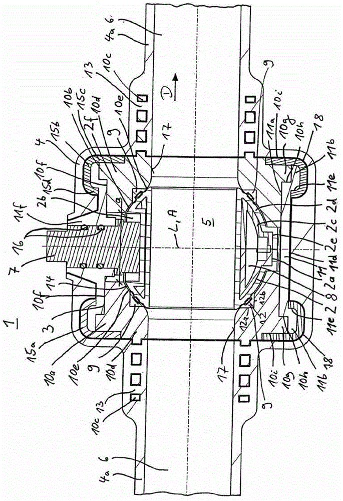
[0020] figure 1 A longitudinal section through a ball valve 1 according to the invention is shown. Seen from the inside to the outside, the ball valve 1 basically consists of a valve ball 2 , a support structure 3 and a housing 4 .

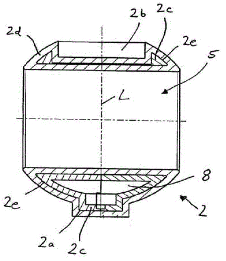
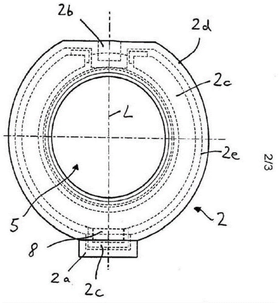
[0021] The valve ball 2 used as a shut-off in the ball valve 1 usually has a central cylindrical through-hole 5 . figure 1 shows that the valve ball 2 is in the open valve position. In this position, the through-opening 5 connects two connecting pipes 4 a arranged opposite to each other, which are integral parts of the housing 4 , so that fluid can flow through the ball valve 1 . In order to be able to move the valve ball 2 from its open valve position to its closed position from the open valve position to the shut-off valve position, it is rotatably mounted in the support structure 3 about an axis A which is vertical in this case. For this purpose, an annular journal 2 a is provided in the region of the lower end of the valve ball 2 , the long...


PUM


Abstract

The plastic valve ball (2) comprises a composite construction unit, which has a carrying element (2c) and a surface layer (2d). A spherical valve ball (1) has a passage opening (5). The plastic valve ball is movably stored between an opening and closing position in a housing (4). The surface layer surrounds the carrying element. The surface layer is coated with a session layer as an adhesion mediator. The carrying element is filled with a cavity (8). Two bearing rings are inserted into an injection mold.

Description

[0001] Cross References to Related Applications [0002] This application is a divisional application of the invention patent application named "plastic ball valve" with the application number 200880017334.2 filed on May 20, 2008 and whose priority date is May 24, 2007. technical field [0003] The invention relates to a valve ball of a ball valve, which has a through hole and is supported in a shell of the ball valve so as to be able to rotate between an open valve position and a closed valve position. Background technique [0004] A ball valve made of plastic and a method for its production are known from European patent EP0575643B1. The ball valve essentially consists of a housing in which a valve ball is mounted as a locking element. The housing has two pipe connections which are usually connected to each other by the through holes of the pipe connections in the open valve position of the valve ball and which are separated from each other by the valve ball in the closed...

Claims


Application Information

Patent Timeline
Patent Type & Authority Applications(China)
IPC IPC(8): F16K5/08
CPCF16K5/0689F16K27/067F16K5/0657Y10T137/7036
Inventor 迈克尔·坦普
Owner MICHAEL TEMPLE
Learn More