
A three-track flap test method for simulating wing deformation

A test method and a technology of three slide rails are applied in the testing of mechanical components, testing of machine/structural components, measuring devices, etc., which can solve problems such as large specific gravity, large test scale, large cost, and high risk, and achieve accuracy improvement, Effects of reducing the size of the experimental design

Active Publication Date: 2016-03-09
XIAN AIRCRAFT DESIGN INST OF AVIATION IND OF CHINA
View PDF5 Cites 0 Cited by
  • Summary
  • Abstract
  • Description
  • Claims
  • Application Information

AI Technical Summary

Problems solved by technology

[0002] In the case of the wing deformation of the three-rail flap, the load will be redistributed among the three rails, and the span-direction stress and strain caused by the deformation of the wing on the flap surface account for a large proportion of the stress of the entire flap. If these are ignored impact, the flap structure will not be adequately assessed
At present, the general method of simulating the wing deflection line adopts the method of box section simulation. During the test process, a separate load needs to be applied to the box section. The test scale and cost are relatively large, and the risk in the test process is relatively high.

Method used


Image

  • A three-track flap test method for simulating wing deformation
  • A three-track flap test method for simulating wing deformation

Examples


Embodiment 1

[0022] The cruising state test of a large transport aircraft flap force transmission characteristic test is carried out, and the method is explained.

[0023] 1) According to the installation requirements of the flaps on the wing in cruise state, install the flaps on three pedestal supports.

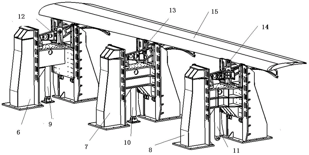
[0024] 2) According to the deformation of the wing, the displacement of the three slide rails at the wing connection point in the cruise state is obtained, and the position of the wing connection point of the three slide rails after deformation in the whole machine coordinate system is obtained;

[0025] 3) Use the relative displacement method to solve the forced displacement that the middle slide rail needs to impose during the test, see figure 1 ;

[0026] 4) Select the displacement actuator 10 in the central plus platform 7 to apply forced displacement according to the needs, see figure 2 ;

[0027] 5) The displacement cylinder 10 applies forced displacement and aerodynamic load t...

Embodiment 2

[0029] The take-off and landing state test of a large transport aircraft flap force transmission characteristic test is carried out, and the method is explained.

[0030] 1) According to the installation requirements of the flaps on the wing in the take-off and landing state, install the flaps on three pedestal supports.

[0031] 2) According to the deformation of the wing, the displacement of the three slide rails at the wing connection point in the take-off and landing state is obtained, and the position of the three slide rail wing connection point after deformation in the whole machine coordinate system is obtained;

[0032] 3) Use the relative displacement method to solve the forced displacement that the middle slide rail needs to impose during the test, see figure 1 ;

[0033] 4) Select the displacement actuators 9 and 11 in the central plus benches 6 and 8 to apply forced displacement according to the needs, see figure 2 ;

[0034] 5) The displacement cylinder 10 ap...


PUM


Abstract

The invention belongs to the technical field of strength tests, and relates to a three-slideway wing flap test method of the strength test under the condition that the wings deform. By utilizing the relative displacement theory, the three-slideway wing flap test method largely reduces the design scale of the experiment, reduces test risks, largely improves the accuracy of the experiment design through the method that forced displacement and pneumatic loads are simultaneously loaded stage by stage, and fully tests the structures like wing flaps.

Description

technical field [0001] The invention belongs to the technical field of strength testing, and relates to a three-sliding-rail flap test method used for the strength test of the three-sliding-rail flap under the condition of wing deformation. Background technique [0002] In the case of the wing deformation of the three-rail flap, the load will be redistributed among the three rails, and the span-direction stress and strain caused by the deformation of the wing on the flap surface account for a large proportion of the stress of the entire flap. If these are ignored impact, the flap structure will not be adequately assessed. At present, the general method of simulating the wing deflection line adopts the method of box section simulation. During the test process, a separate load needs to be applied to the box section. The test scale and cost are relatively large, and the risk in the test process is relatively high. Contents of the invention [0003] The purpose of the inventi...

Claims


Application Information

Patent Timeline
Patent Type & Authority Patents(China)
IPC IPC(8): G01M13/00
Inventor 杜凯范瑞娟李健
Owner XIAN AIRCRAFT DESIGN INST OF AVIATION IND OF CHINA
Learn More