Method for network voltage amplitude, frequency and phase angle detection based on one-phase phase-locked loop algorithm

A grid voltage, phase-locked loop technology, applied in multi-tester circuits and other directions, can solve the problem of inability to obtain grid voltage phase angle, frequency and amplitude information, etc., to eliminate DC offset, avoid influence, and eliminate odd harmonics. wave effect

Inactive Publication Date: 2014-02-05
HARBIN INST OF TECH
View PDF7 Cites 31 Cited by
  • Summary
  • Abstract
  • Description
  • Claims
  • Application Information

AI Technical Summary

Problems solved by technology

[0003] The purpose of the present invention is to solve the problem that the current phase-locked loop voltage detection method cannot obtain accurate phase angle, frequency and amplitude information of the grid voltag

Method used


Image

  • Method for network voltage amplitude, frequency and phase angle detection based on one-phase phase-locked loop algorithm
  • Method for network voltage amplitude, frequency and phase angle detection based on one-phase phase-locked loop algorithm
  • Method for network voltage amplitude, frequency and phase angle detection based on one-phase phase-locked loop algorithm

Examples


specific Embodiment approach 1

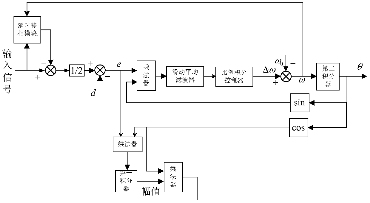
[0021] Specific implementation mode one: combine figure 1 Illustrate the present embodiment, the method for detecting grid voltage amplitude, frequency and phase angle based on the single-phase phase-locked loop algorithm described in the present embodiment, it comprises the following steps:

[0022] Step 1: Collect the grid voltage signal and input it to the delay phase shifting module. The delay phase shifting module simultaneously receives the frequency value of the grid voltage obtained in the previous cycle, and the delay phase shifting module outputs the delay of the grid voltage signal, the collected grid voltage signal is subtracted from the delay signal of the grid voltage, and the obtained result is divided by 2 to obtain a grid voltage signal without DC offset;

[0023] Step 2: Use the grid voltage signal without DC offset obtained in step 1 as the input signal of the enhanced phase-locked loop to obtain the amplitude of the grid voltage in this cycle, the frequency...

specific Embodiment approach 2

[0036] Specific embodiment 2: This embodiment is a further limitation of the method for detecting grid voltage amplitude, frequency and phase angle based on the single-phase phase-locked loop algorithm described in specific embodiment 1. In the step 2, the step 1 is obtained The grid voltage signal without DC offset is used as the input signal of the enhanced phase-locked loop, and the method of obtaining the amplitude of the grid voltage of this cycle, the frequency value of the grid voltage of this cycle and the phase angle value of the grid voltage of this cycle is as follows:

[0037] Step A1: Multiply the magnitude of the grid voltage obtained in the previous cycle by the cosine value of the phase angle of the grid voltage obtained in the previous cycle to obtain a signal d, and subtract the grid voltage signal obtained in step 1 without DC offset from the Signal d, to obtain the phase-locked error e of the grid voltage signal;

[0038] Step B1: Multiply the phase-lock er...

specific Embodiment approach 3

[0041] Specific embodiment three: this embodiment is a further limitation of the method for detecting grid voltage amplitude, frequency and phase angle based on the single-phase phase-locked loop algorithm described in specific embodiment one, and step one is obtained in step two The grid voltage signal without DC offset is used as the input signal of the enhanced phase-locked loop, and the method of obtaining the amplitude of the grid voltage of this cycle, the frequency value of the grid voltage of this cycle and the phase angle value of the grid voltage of this cycle is as follows:

[0042] Step A2: Multiply the magnitude of the grid voltage obtained in the previous cycle by the cosine value of the phase angle of the grid voltage obtained in the previous cycle to obtain a signal d, and subtract the grid voltage signal obtained in step 1 without DC offset from the Signal d, to obtain the phase-locked error e of the grid voltage signal;

[0043] Step B2: Multiply the phase-lo...


PUM


Abstract

The invention discloses a method for network voltage amplitude, frequency and phase angle detection based on the one-phase phase-locked loop algorithm. According to the method, accurate amplitude, frequency and phase angle detection is achieved when direct current offset and harmonic waves exist in a one-phase power grid. The method comprises the steps that a network voltage signal is acquired and transmitted to a delay phase-shifting module; the delay phase-shifting module receives a network voltage frequency value obtained from the last cycle at the same time and outputs a network voltage delay signal; subtraction is carried out on the acquired network voltage signal and the network voltage delay signal to obtain a result, and the result is divided by 2 to obtain a network voltage signal free of direct current offset; the network voltage signal free of direct current offset is taken as an input signal of an enhanced phase-locked loop, and then the network voltage amplitude value, frequency value and phase angle value of the cycle are obtained. The method for network voltage amplitude, frequency and phase angle detection based on the one-phase phase-locked loop algorithm is suitable for the field of conversion of electrical energy.

Description

technical field [0001] The invention relates to a method for detecting the voltage amplitude, frequency and phase angle of a single-phase grid, in particular to a method for detecting the voltage amplitude, frequency and phase angle of the grid based on a single-phase phase-locked loop algorithm. Background technique [0002] With the rapid development of the application of new energy power generation in the civil field, single-phase grid-connected inverter technology has been paid more and more attention. In the single-phase grid-connected inverter, the phase-locked loop technology is usually used to obtain the amplitude, frequency and phase of the grid voltage, so as to control the grid-connected current in real time. Therefore, the precision and dynamic response performance of the phase-locked loop algorithm directly determine the control performance of grid-connected current. In the actual system, the power grid is not an ideal sine wave, but there are a lot of harmonic...

Claims


Application Information

Patent Timeline
IPC IPC(8): G01R15/12
Inventor 骆素华吴凤江骆林松张陆捷冯帆
Owner HARBIN INST OF TECH
Why Eureka
Try Eureka