Zero-voltage control circuit for small signals

A zero-voltage control and micro-signal technology, which is applied in the control field, can solve problems such as high input signal requirements, circuit interference, and micro-signals that cannot be zero-voltage, and achieve high detection accuracy and zero-voltage control.

Active Publication Date: 2014-02-05
STATE GRID CORP OF CHINA +1
View PDF4 Cites 4 Cited by
  • Summary
  • Abstract
  • Description
  • Claims
  • Application Information

AI Technical Summary

Problems solved by technology

[0005] 1. The requirements for the input signal are high, the voltage must be above 0.7V, and the current is at the mA level;
[0006] 2. The accuracy of zero-crossing detection is low. Since the voltage drop of the diode is about 0.7V, the detection signal is offset, so the zero-voltage position detected by the

Method used


Image

  • Zero-voltage control circuit for small signals
  • Zero-voltage control circuit for small signals

Examples


Embodiment Construction

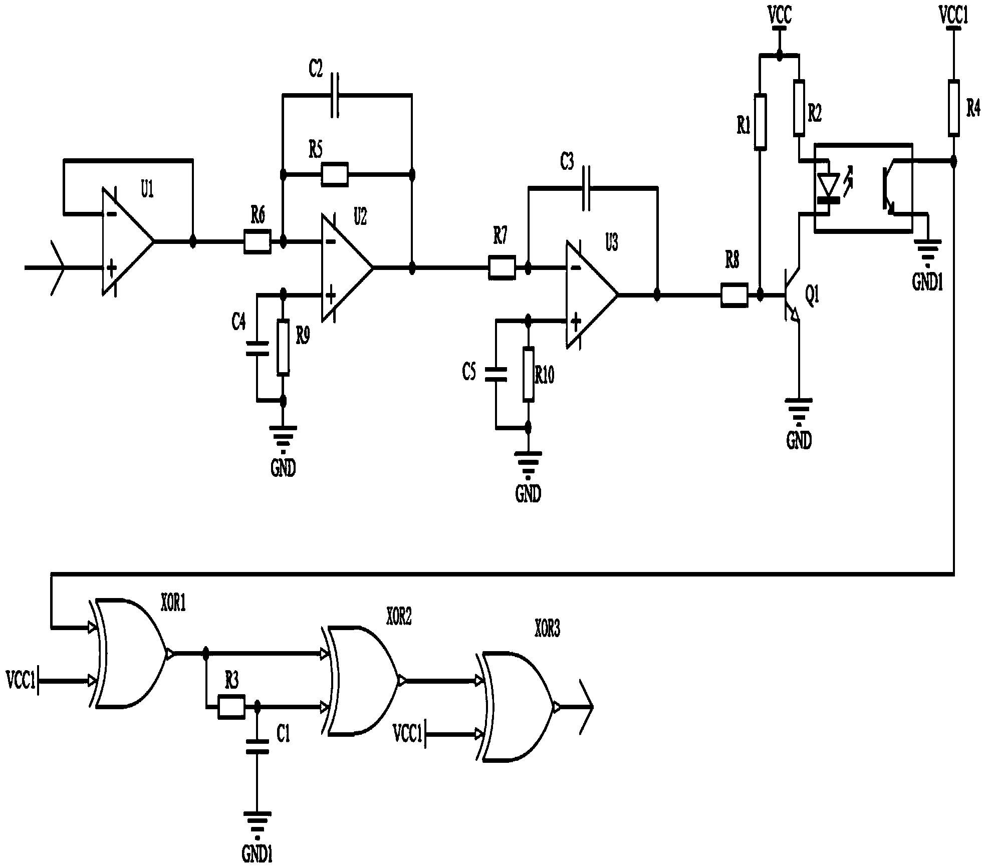
[0019] Such as figure 1 As shown, the zero voltage control circuit for tiny signals of the present invention includes:

[0020] The first operational amplifier U1, the second operational amplifier U2, the third operational amplifier U3, the first resistor R1, the second resistor R2, the third resistor R3, the fourth resistor R4, the fifth resistor R5, the sixth resistor R6, the seventh resistor Resistor R7, eighth resistor R8, ninth resistor R9, tenth resistor R10, first capacitor C1, second capacitor C2, third capacitor C3, fourth capacitor C4, fifth capacitor C5, first transistor Q1, first XOR gate XOR1, second XOR gate XOR2, third XOR gate XOR3, optocoupler, first power supply Vcc and second power supply Vcc1.

[0021] The first operational amplifier U1 constitutes a voltage follower, thereby forming an anti-interference isolation protection device for isolating the input signal from the signal source circuit and eliminating the influence of the zero-voltage control circui...


PUM

PropertyMeasurementUnit
Resistanceaaaaaaaaaa
Capacitanceaaaaaaaaaa

Abstract

The invention relates to a zero-voltage control circuit for small signals. The circuit comprises a first operational amplifier, a second operational amplifier, a third operational amplifier, a first resistor, a second resistor, a third resistor, a fourth resistor, a fifth resistor, a sixth resistor, a seventh resistor, an eighth resistor, a ninth resistor, a tenth resistor, a first capacitor, a second capacitor, a third capacitor, a fourth capacitor, a fifth capacitor, a first transistor, a first exclusive-OR gate, a second exclusive-OR gate, a third exclusive-OR gate, an optical coupler, a first power source and a second power source. The zero-voltage control circuit for the small signals achieves zero-voltage detection on the small signals, detection accuracy is high, various isolation protection means are adopted, and therefore no interference will happen to an external circuit, the signal deviation problem does not exist, and zero-voltage control over data output is achieved well.

Description

technical field [0001] The invention relates to the field of control, in particular to a zero-voltage control circuit for tiny signals. Background technique [0002] Zero voltage control technology is a kind of soft switching technology, which is mainly used to protect MOSFET, electromagnetic relay, thyristor, IGBT and other switching tubes from high voltage impact. [0003] Common zero-voltage control circuits currently using zero-voltage control technology such as figure 1 shown. [0004] The input signal is directly connected to two optocouplers (such as pc817) for zero voltage detection. The defect of this circuit is also obvious. [0005] 1. The requirements for the input signal are high, the voltage must be above 0.7V, and the current is at the mA level; [0006] 2. The accuracy of zero-crossing detection is low. Since the voltage drop of the diode is about 0.7V, the detection signal is offset, so the zero-voltage position detected by the circuit is actually the pos...

Claims


Application Information

Patent Timeline
IPC IPC(8): G01R19/175
Inventor 陈燕生王启银周国华池远帆白英王忠贺伟文
Owner STATE GRID CORP OF CHINA
Why Eureka
Try Eureka