Node failure recovery method for micro network

A network node, fault recovery technology, applied in the direction of data exchange network, digital transmission system, electrical components, etc., can solve the time and efficiency can not meet the rapid and reasonable recovery of complex micro-network failure, failure recovery method is inefficient, failure recovery experience Inability to form effective accumulation and other problems, to achieve the effect of quickly and efficiently recovering faults, reducing losses, and shortening fault recovery time

Active Publication Date: 2014-02-05
广州捷能电力科技有限公司
View PDF5 Cites 15 Cited by
  • Summary
  • Abstract
  • Description
  • Claims
  • Application Information

AI Technical Summary

Problems solved by technology

[0002] In the power network, the traditional fault recovery methods for complex micro-networks are only suitable for linear programming, artificial intelligence optimization algorithms and heuristic methods
The traditional fault recovery method requires power flow calculations to verify the feasibility of each solution, so a large amount of calculation is required, so it is often unable to meet the requirements of complex micro-networks for fast and reasonable recovery of faults in terms of time and efficiency.
[0003] With the development of communication and automation technology and the construction and transformation of power equipment, the current grid network structure dominated by complex micro-networks has become more and more complex. Relying on manpower alone can no longer meet the needs of development, and this fault recovery The method is inefficient and cannot form an effective accumulation of effective fault recovery experience
However, the use of some artificial intelligence optimization algorithms mentioned above involves a large amount of calculations, which cannot meet the requirements of fast, effective and reasonable

Method used


Image

  • Node failure recovery method for micro network
  • Node failure recovery method for micro network
  • Node failure recovery method for micro network

Examples


Embodiment Construction

[0019] The technical solution of the present invention will be further described in detail below in conjunction with the drawings and specific embodiments.

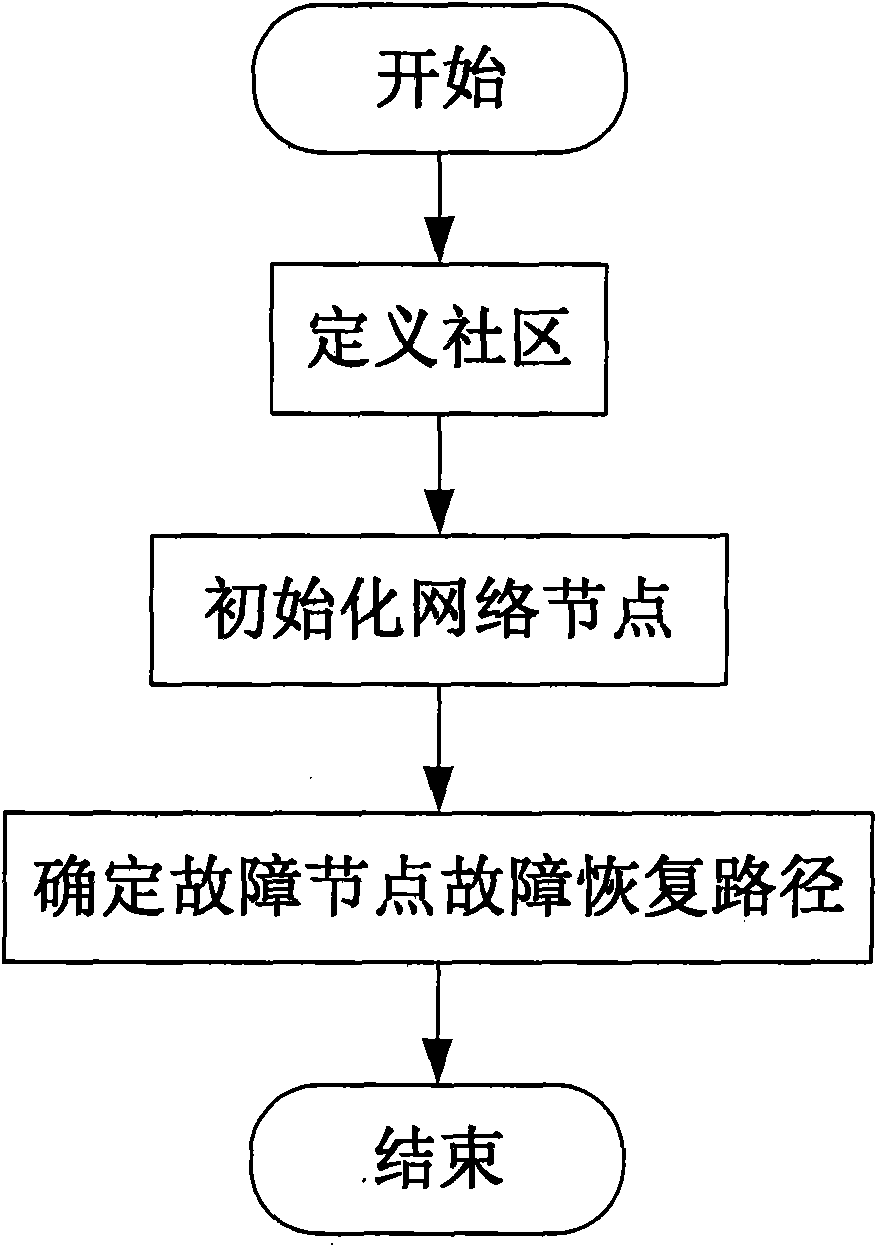
[0020] The node failure recovery method in the micro network provided by the present invention includes the following steps, such as figure 1 Shown:

[0021] Define the community: divide each network node in the above micro network into different communities, and set the same community identifier for the network nodes divided into the same community;

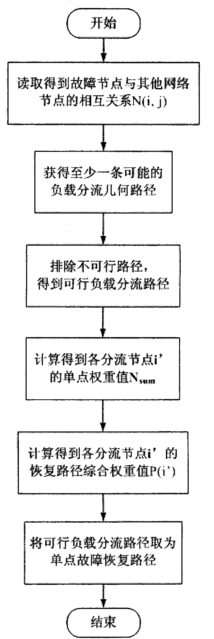
[0022] Initialize the network node: According to the mutual relationship of the network nodes in the same community, set the network node role, network node attributes, and network node field for each network node; and pre-calculate the single-point failure recovery path of each network node;

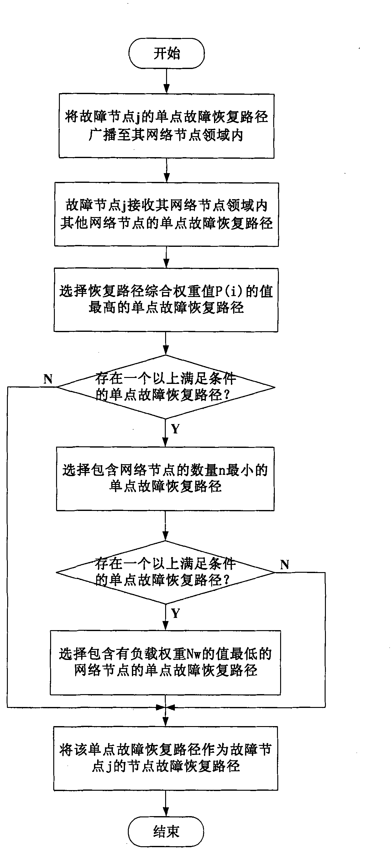
[0023] Determine the node failure recovery path: When a network node in the community fails, perform a single point of failure negotiation process to determine the node failure recovery path ...


PUM


Abstract

The invention provides a node failure recovery method for a micro network. The method comprises the following steps that cells are defined, namely, network nodes are classified into different cells, and the same community is set for the nodes classified in the same cell; the network nodes are initialized, namely, according to the mutual relations among the nodes in the same cell, network node roles, network node attributes and network node fields are set, and a single point failure recovery path of each node is precomputed; node failure recovery paths are determined; namely, when any node in the cells has failures, a single point failure negotiation process is carried out; when a plurality of nodes have failures, a failure recovery path dynamic calculation process and a multipoint failure negotiation process are carried out on each failure node in sequence. The node failure recovery method for the micro network is realized on the basis of the thought of local optimum and collective wisdom and efforts, and can rapidly and effectively recovery single point failures, rapidly recovery multipoint failures in the mode of local optimum, avoid tedious calculation and effectively accumulate failure removing experience.

Description

Technical field [0001] The present invention relates to the field of complex micro-networks, in particular to the improvement of a fault recovery method for a "grid type" complex micro-network. Background technique [0002] In power networks, traditional failure recovery methods for complex micro-networks are only suitable for linear programming, artificial intelligence optimization algorithms and heuristic methods. The use of traditional fault recovery methods requires power flow calculations to verify the feasibility of each solution, so a large number of calculations are required, so the time and efficiency often cannot meet the requirements of complex micro-networks to quickly and reasonably recover from faults. [0003] With the development of communication and automation technology and the construction and transformation of power equipment, the current grid network structure dominated by complex micro-networks has become more and more complex, and only relying on manpower can...

Claims


Application Information

Patent Timeline
Patent Type & Authority Applications(China)
IPC IPC(8): H04L12/703H04L45/28
Inventor 赖金涛
Owner 广州捷能电力科技有限公司
Why Eureka
Try Eureka