Dynamic balance structure

A spindle and chute technology, applied in metal processing machinery parts, maintenance and safety accessories, metal processing equipment, etc., can solve problems such as unstable operation, heavy motor load, and complicated calibration procedures

Active Publication Date: 2014-02-12
杨孝晟
View PDF9 Cites 4 Cited by
  • Summary
  • Abstract
  • Description
  • Claims
  • Application Information

AI Technical Summary

Problems solved by technology

[0002] Press, generally such as grinding machines, lathes, milling machines and other machine tools, which mainly use a spindle to drive a base for clamping workpieces, and drive the base and the workpiece to rotate through high-speed rotation for processing, but these workpieces or bases During the production process or other external factors, the center of gravity may be shifted due to a slight error value. Although these tools or bases may only have a small deviation value, the centrifugal force may still make these tools or bases In the case of high-speed rotation, the tool vibrates violently due to the offset of the center of gravity, making the overall operation unstable when rotating
[0003] For example, No. M306910 patent of Taiwan, China, a dynamic balance ring is sleeved on a tool seat, and the tool seat is used to connect a cutting tool, and the dynamic balance ring is fixed on the tool seat by a plurality of fixing parts. The tool seat and the cutting tool can be driven by the machine tool to rotate for processing, but the dynamic balance ring of this structure is additionally sleeved on the tool seat, so that when the machine tool drives the tool seat and the When the cutting tool rotates, the motor of the machine tool has to bear the weight of the dynamic balance ring, which often causes the motor to be overloaded and reduces the cutting capacity. Further, it may be easily damaged, and when the dynamic balance ring is installed on the tool seat When the tool seat is installed on the main machine, the center of gravity may still shift and a second calibration is required, which will cause the calibration procedure to be too complicated and reduce its work efficiency. Therefore, the existing dynamic balance structure is still Not yet ideal, still needs to be discussed by people in the industry

Method used


Image

  • Dynamic balance structure
  • Dynamic balance structure
  • Dynamic balance structure

Examples


Embodiment Construction

[0034] The following examples illustrate possible implementations of the present invention, but are not intended to limit the protection scope of the present invention.

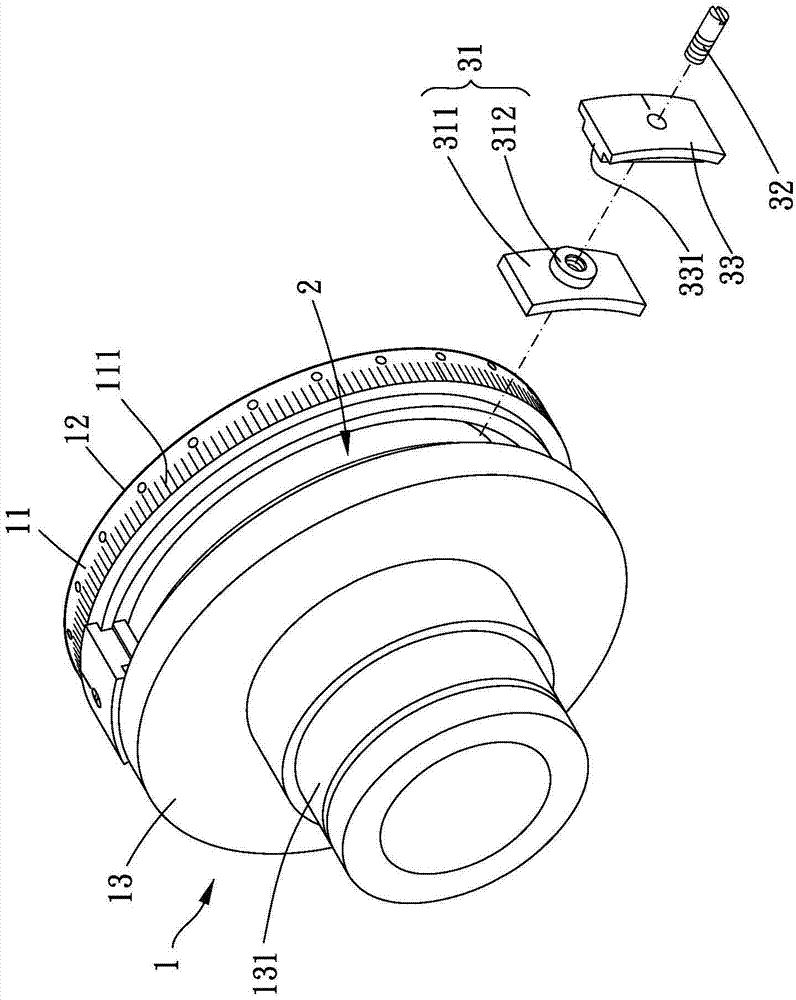
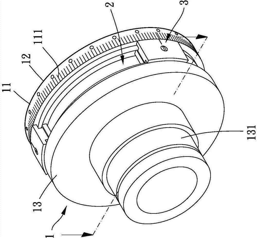
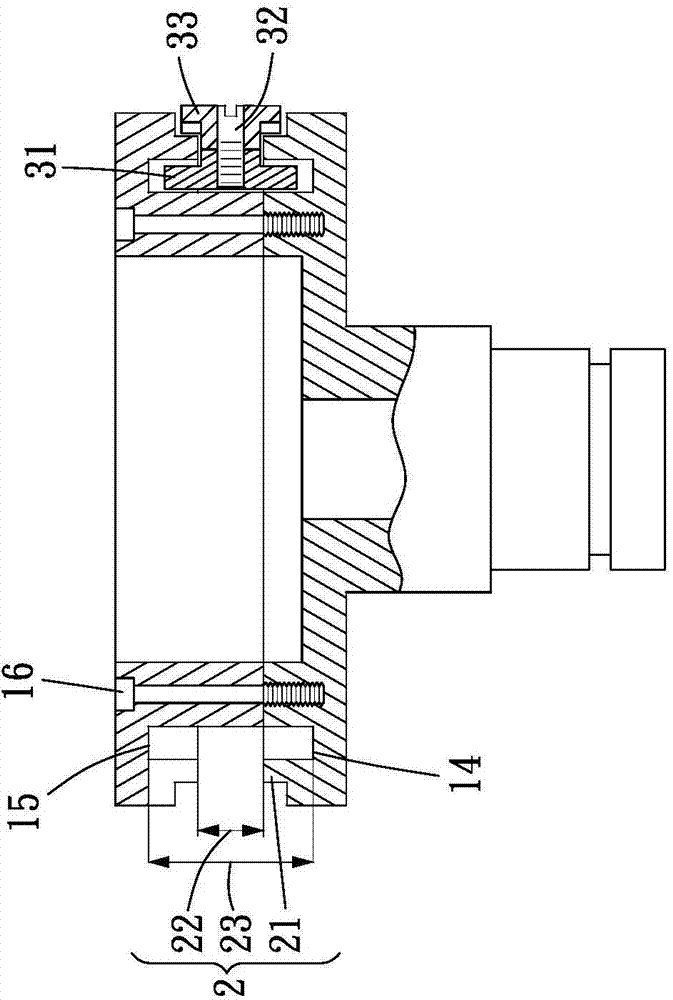
[0035] Please refer to Figure 1 to Figure 4 , the present invention provides a dynamic balance structure for setting on a machine tool (not shown), the machine tool includes a main shaft 4, the main shaft 4 defines a central axis, the dynamic balance structure includes a clamping part 1, a The chute 2 and at least one counterweight assembly 3 .

[0036]The clamping part 1 is coaxially arranged on the main shaft 4 with one end thereof, and the opposite end of the clamping part 1 is used for connecting a workpiece to be rotated (not shown in the figure), and the clamping part 1 has a The outer ring surface 11 of the clamping member 1 is a ring body and has a first face 12 and a second face 13 opposite to each other. The first face 12 of the clamping member 1 and the second face The surface 13 is perpendicula...


PUM


Abstract

The invention provides a dynamic balance structure. The dynamic balance structure comprises a clamping component, a slide groove and at least one counterweight component, wherein the clamping component is arranged on a main shaft of a working mother machine; the main shaft defines a middle shaft; the clamping component is provided with an outer ring surface surrounding the middle shaft; the slide groove is arranged around the outer ring surface of the clamping component; at least one flange is arranged on the inner side wall of the slide groove in a protruding way; the counterweight component comprises an inner slide block and a compacting component; the inner slide block is movably arranged in the slide groove; the compacting component penetrates through the inner slide block and can compact the inner slide block towards the flange, so that the inner slide block cannot move along the slide groove. By the dynamic balance structure provided by the invention, the working mother machine can be prevented from being damaged by over high load of a motor without additionally adding weight to the working mother machine.

Description

technical field [0001] The invention relates to a dynamic balance structure, in particular to a dynamic balance structure which can improve the precision of a processing tool. Background technique [0002] Press, generally such as grinding machines, lathes, milling machines and other machine tools, which mainly use a spindle to drive a base for clamping workpieces, and drive the base and the workpiece to rotate through high-speed rotation for processing, but these workpieces or bases During the production process or other external factors, the center of gravity may be shifted due to a slight error value. Although these tools or bases may only have a small deviation value, the centrifugal force may still make these tools or bases When the tool is rotating at a high speed, it will vibrate violently due to the offset of the center of gravity, making the overall operation unstable when rotating. [0003] For example, No. M306910 patent of Taiwan, China, a dynamic balance ring i...

Claims


Application Information

Patent Timeline
Patent Type & Authority Applications(China)
IPC IPC(8): B23Q11/00
CPCB23Q11/0021B23Q11/0035
Inventor 杨孝晟
Owner 杨孝晟
Why Eureka
Try Eureka