Method of assembling a frame assembly of a compressor

An assembly method and compressor technology, applied in the field of compressors, can solve the problems of insufficient sealing distance between the piston and the cylinder, affecting the service life of the compressor, unfavorable product model expansion, etc. low quality effect

Inactive Publication Date: 2016-04-13
ZHUHAI GREE REFRIGERATION TECH CENT OF ENERGY SAVING & ENVIRONMENTAL PROTECTION
View PDF7 Cites 0 Cited by
  • Summary
  • Abstract
  • Description
  • Claims
  • Application Information

AI Technical Summary

Problems solved by technology

However, when the U-shaped groove is opened on the cylinder, the processed tool is subjected to uneven force, which seriously affects the cylindricity of the cylinder; and due to the existence of the U-shaped groove, the thermal deformation of the cylinder is asymmetrical during operation, which affects the service life of the compressor.
At the same time, when the product model is expanded, the sealing distance between the piston and the cylinder is likely to be insufficient, which limits the piston stroke and poor versatility, which is not conducive to product model expansion

Method used


Image

  • Method of assembling a frame assembly of a compressor
  • Method of assembling a frame assembly of a compressor
  • Method of assembling a frame assembly of a compressor

Examples


Embodiment Construction

[0031] In order to make the purpose, technical solution and advantages of the present invention clearer, the method for assembling the frame assembly of the compressor of the present invention will be further described in detail below with reference to the drawings and embodiments, taking the cylindrical piston as an example. It should be understood that the specific embodiments described here are only used to explain the present invention, and are not intended to limit the use of the cylindrical piston in the frame assembly of the compressor described in the present invention.

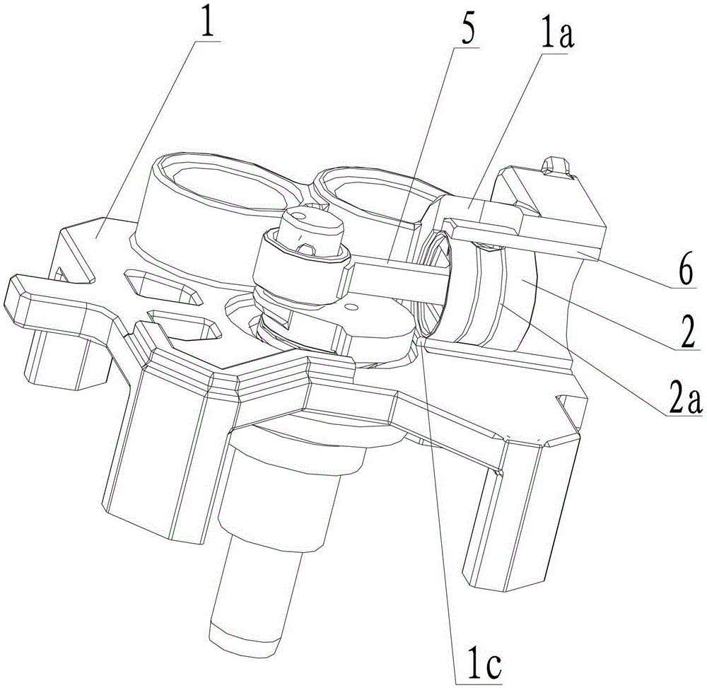
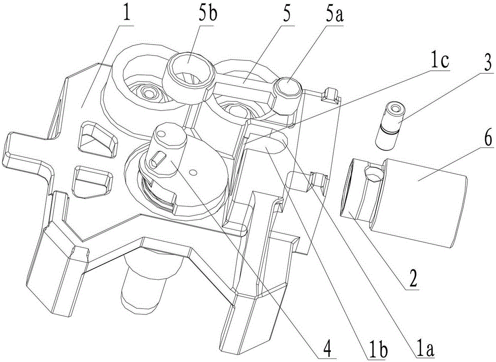
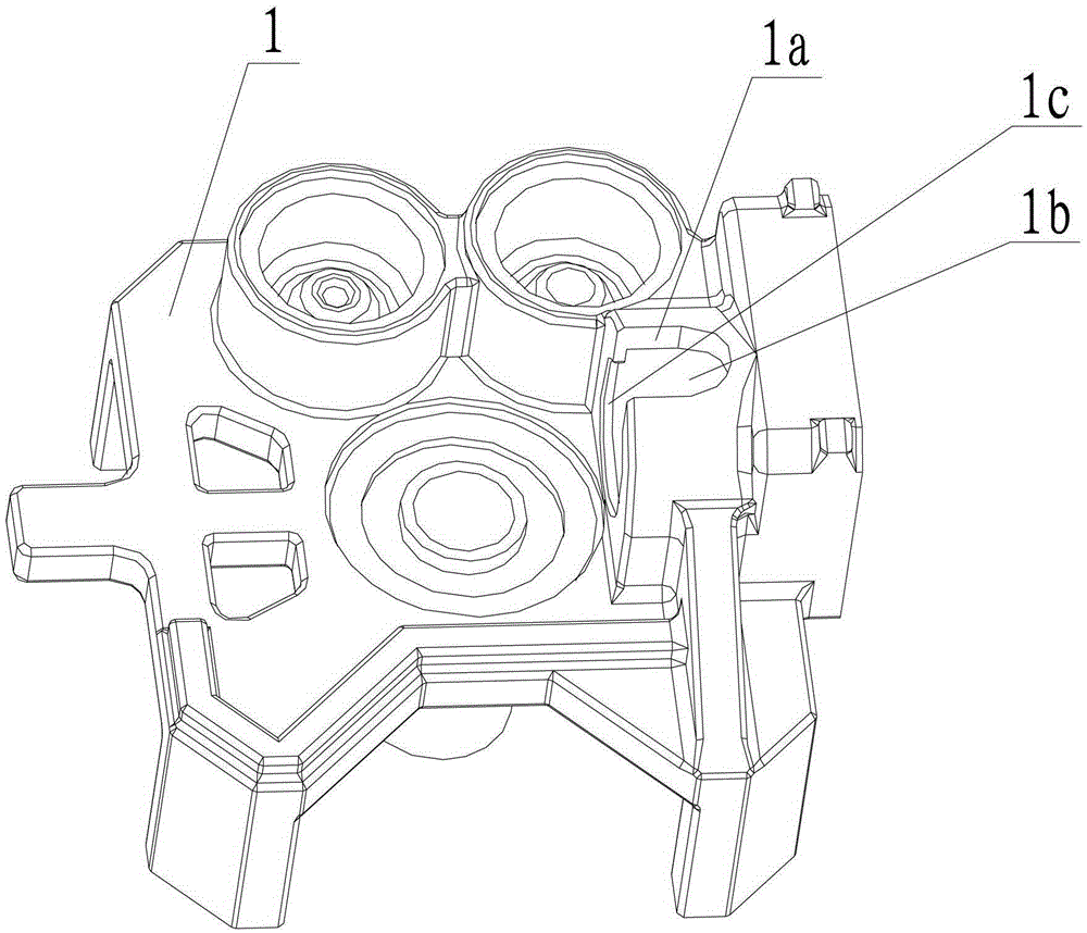
[0032] refer to Figure 1 to Figure 4 , the frame assembly includes frame 1, crankshaft 4, connecting rod 5, piston 2 and cylinder 6, frame 1 and cylinder 6 adopt a split structure, that is, frame 1 and cylinder 6 are manufactured independently, cylinder 6 and frame 1 The connection and fixing method is bolt connection, welding connection or rivet connection, and the valve plate end cover (not shown) ...


PUM


Abstract

The invention relates to a rack assembly for a compressor; the rack assembly comprises a cylinder and a rack; a cylinder insertion hole is formed in the rack; a first end part of the cylinder insertion hole is provided with a U-shaped slot; the cylinder is mounted in the cylinder insertion hole. The invention also relates to an assembling method. Unfavorable influences such as cylinder deformation caused by the fact that a U-shaped slot is formed in the cylinder are avoided, the machining deformation of the cylinder is reduced, and the cylinder precision is improved; the sealing distance on the cylinder is increased, the sealing effect is improved, the universality is strong, and model expansion is convenient; besides, the split cylinder is smaller in mass and shape, so large-batch machining is facilitated, the machining efficiency is improved, and the machining cost is reduced; a piston mounted in the cylinder can be very easily assembled onto a crankshaft by a connection rod, so the production efficiency is improved.

Description

technical field [0001] The invention relates to the field of compressors, in particular to an assembly method of a frame assembly of a compressor. Background technique [0002] In traditional compact crankshaft-connecting rod compressors, in order to meet the requirements of miniaturization, the frame and cylinder of the compressor adopt an integrated structure, and the distance between the end surface of the cylinder near the end of the crankshaft and the crankshaft needs to be designed to be less than Linkage distance. Therefore, in order to connect the two ends of the connecting rod to the crankshaft and the piston in the cylinder respectively, it is usually necessary to open a U-shaped groove on the upper part of the end of the cylinder close to the crankshaft, so that the connecting rod is installed from top to bottom, and one end is sleeved on the crankshaft. , one end is put into the cylinder and connected with the piston. However, when the U-shaped groove is opened...

Claims


Application Information

Patent Timeline
Patent Type & Authority Patents(China)
IPC IPC(8): F04B39/00
Inventor 周宙崔中严耀宗赵文钊魏会军
Owner ZHUHAI GREE REFRIGERATION TECH CENT OF ENERGY SAVING & ENVIRONMENTAL PROTECTION
Why Eureka
Try Eureka