A structure of led energy-saving lamp

A technology of LED energy-saving lamps and LED light strips, applied in lighting applications, lighting and heating equipment, office buildings, etc., can solve the problems of inconvenient disassembly and maintenance, complex internal connection structure, and large loss of lamps, and achieve Save labor costs and capital costs, strong detachability, and material saving effects

Active Publication Date: 2016-01-20
广东井本实业有限公司
View PDF6 Cites 0 Cited by
  • Summary
  • Abstract
  • Description
  • Claims
  • Application Information

AI Technical Summary

Problems solved by technology

[0002] At present, the use of LED lights is becoming more and more widespread, not only in people's daily life, but also in industrial production. For example, they are widely used in chemical companies or textile factory production workshops. For this reason, some lamps The manufacturer has developed a closed lamp that is especially suitable for the above-mentioned places. Although it can overcome the weakness of the exposed light bar lamp, due to long-term use, the loss of the lamp is relatively large, and the parts inside need to be replaced frequently. The internal connection structure of this kind of lamp is still relatively complicated, the structural strength is low, the disassembly and maintenance are not very convenient, and the cost of the whole lamp is relatively high

Method used


Image

  • A structure of led energy-saving lamp
  • A structure of led energy-saving lamp
  • A structure of led energy-saving lamp

Examples


Embodiment 1

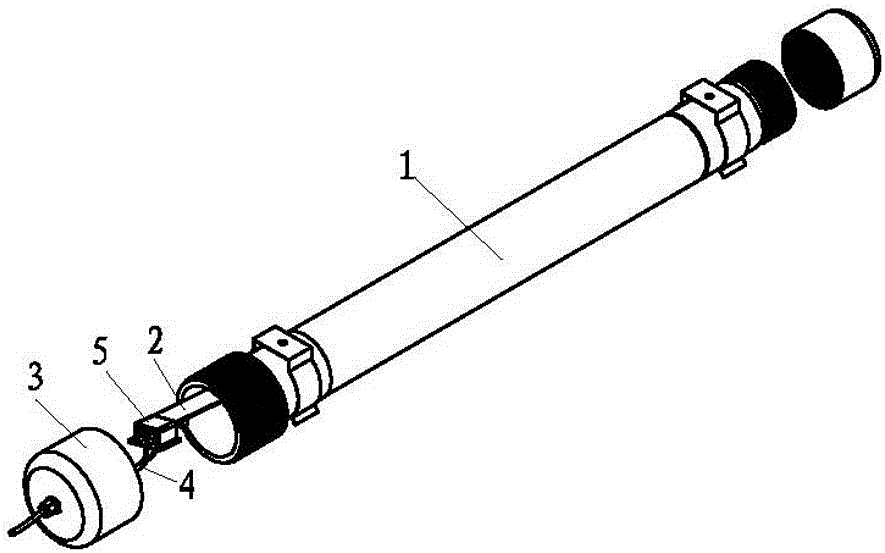
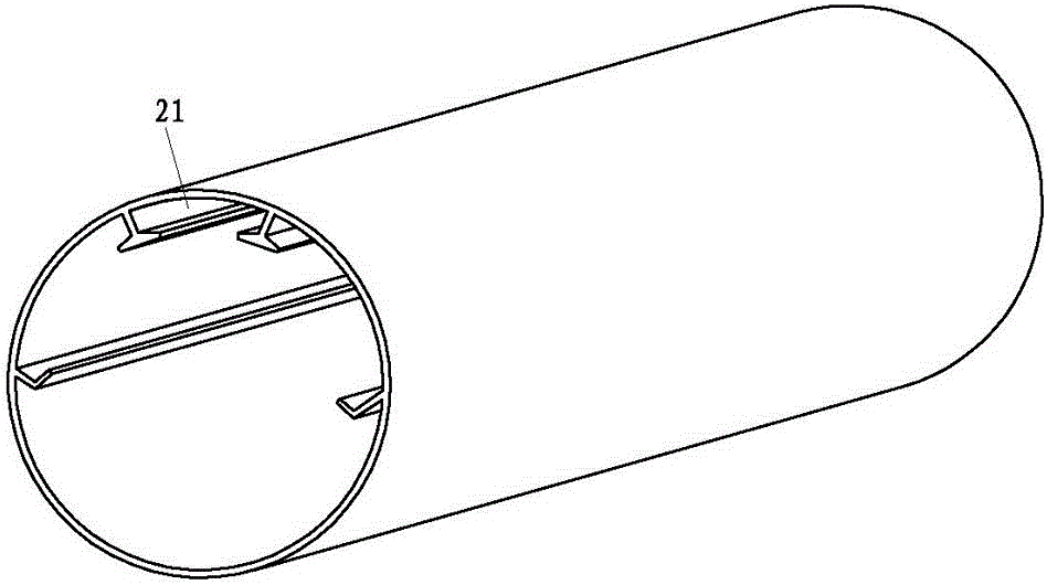
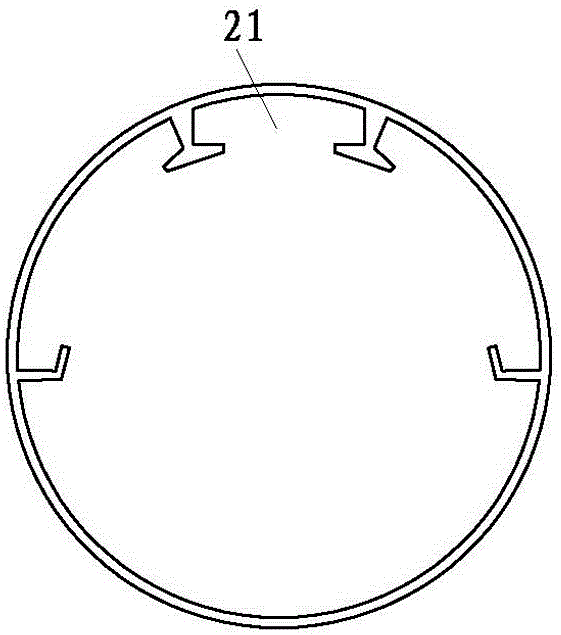
[0042] Such as figure 1 , 2 , 3, 4, 5, 6, 7, 8, 9, 10, 11, and 12, a LED energy-saving lamp structure, including an outer cover 1, an LED light bar 2 arranged in the outer cover 1, the outer cover 1 End caps 3 are provided at both ends, and the LED light bar slot 21 for positioning the LED light bar 2 is arranged inside the outer cover 1, and the positive and negative terminals of one end of the LED light bar 2 are provided with a positive contact 201 and a negative contact 202, the end cover 3 near the end of the LED light bar 2 with the positive contact 201 and the negative contact 202 is provided with a power line 4 passing through the end cover 3, the positive contact 201 and the negative contact 202 are connected to the power line 4 is a detachable electrical conduction. The outer cover 1 and the end cover 3 are fixedly connected together through a connecting pipe. One end of the connecting pipe and the end cover 3 can be connected in a threaded manner for easy disassemb...

Embodiment 2

[0051] Such as Figure 13 As shown, the difference between it and Embodiment 1 is that: between the metal sheet winding plate 513 and the upper tank partition 5101, there is a space 512 for separating the metal sheet intermediate winding space 512 into two or more metal sheet intermediate winding subspaces 5120. The transition winding plate 514 in the middle of the metal sheet.

Embodiment 3

[0053] Such as Figure 14 , 15 , 16, the difference between it and Embodiment 1 is that the metal sheet installation structure is different, and the metal sheet installation structure includes a winding plate for forming the insertion slot 51 and allowing the metal sheet 53 to wind into the insertion slot 51 511 and the metal sheet winding hole 5110 opened on the winding plate 511 . The winding plate 511 is provided with an arc-shaped winding segment 5111 .


PUM


Abstract

The invention relates to the field of lamps and in particular to an LED energy saving lamp structure. The LED energy saving lamp structure comprises an outer cover and an LED lamp strip arranged in the outer cover. End covers are arranged at the two ends of the outer cover, an LED lamp strip insertion groove for locating the LED lamp strip is formed in the outer cover, and a positive terminal and a negative terminal at one end of the LED lamp strip are provided with a positive pole contact and a negative pole contact. The end cover close to the end, provided with the positive pole contact and the negative pole contact, of the LED lamp strip is provided with a power line penetrating through the end cover. The positive pole contact and the negative pole contact are in electric conduction with the power line in a detachable mode, and the structure is simple and firm, low in cost and convenient to disassemble, assemble and maintain.

Description

technical field [0001] The invention relates to the field of lamps, in particular to a structure of an LED energy-saving lamp. Background technique [0002] At present, the use of LED lights is becoming more and more widespread, not only in people's daily life, but also in industrial production. For example, they are widely used in chemical companies or textile factory production workshops. For this reason, some lamps The manufacturer has developed a closed lamp that is especially suitable for the above-mentioned places. Although it can overcome the weakness of the exposed light bar lamp, due to long-term use, the loss of the lamp is relatively large, and the parts inside need to be replaced frequently. The internal connection structure of this lamp is relatively complicated, the structural strength is low, disassembly and maintenance are not very convenient, and the cost of the entire lamp is relatively high. Contents of the invention [0003] The object of the present i...

Claims


Application Information

Patent Timeline
Patent Type & Authority Patents(China)
IPC IPC(8): F21K9/00F21V19/00F21V23/00F21V23/06F21W131/402F21Y115/10F21K9/272F21K9/278F21Y103/10
Inventor 王培清
Owner 广东井本实业有限公司
Why Eureka
Try Eureka