Middle driving type dense bead shaft system mechanism

An intermediate drive, dense bead technology, used in bearing components, shafts and bearings, machinery and equipment, etc., can solve the problem of not meeting the special requirements of intermediate drive machinery and equipment, and achieve the benefits of bearing life, reducing processing difficulty, and ensuring size. and the effect of geometric precision

Inactive Publication Date: 2013-04-03
CHINA PRECISION ENG INST FOR AIRCRAFT IND AVIC
View PDF5 Cites 12 Cited by
  • Summary
  • Abstract
  • Description
  • Claims
  • Application Information

AI Technical Summary

Problems solved by technology

Some existing dense bead shafting designs are top drive types with relatively simple structure, which are generally used for the transition of optical microscope precision rotation drive, and cannot meet the special requirements of intermediate drive mechanical equipment

Method used


Image

  • Middle driving type dense bead shaft system mechanism
  • Middle driving type dense bead shaft system mechanism
  • Middle driving type dense bead shaft system mechanism

Examples


Embodiment Construction

[0043] Below in conjunction with embodiment and accompanying drawing, the present invention will be further described:

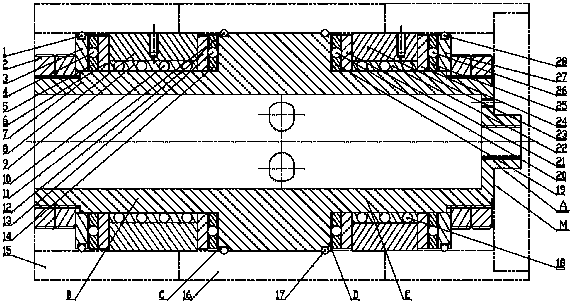
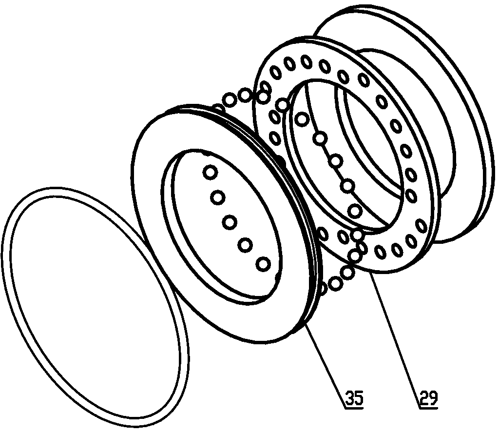
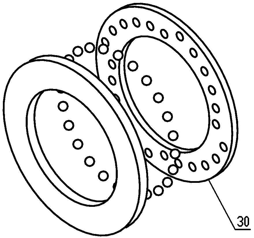
[0044] see figure 1 , which is a structural schematic diagram of the first embodiment of the intermediate drive type dense ball shafting mechanism of the present invention. The intermediate drive type dense ball shafting mechanism includes the axial thrust dense ball shafting I29 (see figure 2 ), axial thrust dense ball shafting II30 (see image 3 ), axial thrust dense ball shafting III31 (see Figure 4 ), axial thrust dense ball shafting IV32 (see Figure 5 ) and radial dense ball shafting I33 (see Image 6 ), radial dense ball shafting II34 (see Figure 7 ), transmission shaft 7 and round nut 2,

[0045] see figure 1 and figure 2 ,and figure 2It is a three-dimensional structure schematic diagram of the axial thrust dense ball shafting I of the intermediate drive type dense ball shafting mechanism of the present invention. The axial thrust dens...


PUM


Abstract

The invention belongs to the field of a numerical control precise measuring device, and relates to a middle driving type dense bead shaft system mechanism. The middle driving type dense bead shaft system mechanism comprises four axial thrust dense bead shaft systems and two radial dense bead shaft systems, a transmission shaft and a locking member. The four axial thrust dense bead shaft systems are arranged on both sides of a middle step shaft. The radial dense bead shaft systems are respectively arranged between the two axial thrust dense bead shaft systems. The end faces of the bearing retainer rings of the axial thrust dense bead shaft systems close to the radial dense bead shaft systems and the end faces of the radial dense bead shaft systems and a retaining frame which are coplanar are coplanar. The transmission shaft is in threaded connection with a revolving member through a screw and maintains a relatively unchanged position relation with the revolving member through a cylindrical pin. The shaft sleeve is in threaded connection to a fixed piece through a screw. The maximum rigidity/inertia ratio is guaranteed, the resistance to overturn is strong, the revolving precision is high, the stress is uniform, and the positioning precision can reach 1'. The processing difficulty is reduced, and the size and geometric accuracy of a ball working rollaway nest are easy to guarantee.

Description

technical field [0001] The invention belongs to the field of numerical control precision measuring equipment, and relates to an intermediate drive type dense ball shafting mechanism. Background technique [0002] At present, the articulated arm measuring instruments produced by domestic and foreign manufacturers generally use ordinary ball bearings as the steering tools between the joints, and all of them adopt asymmetric structure layout. Ordinary ball bearings have the limitation of low repeatability of operation. When the working load increases or there is vibration, the pressure on a single ball will increase, making the balls easily crushed; the shaft system with asymmetric structure will make the bearing less stressed. Uniform, the axis of rotation of the shafting is not fixed, the wear of the bearing increases, and the accuracy of the shafting is difficult to guarantee. Therefore, the common shafting structure arranged asymmetrically will cause a large reading error ...

Claims


Application Information

Patent Timeline
Patent Type & Authority Applications(China)
IPC IPC(8): F16C35/12F16C33/38
Inventor 郭霞
Owner CHINA PRECISION ENG INST FOR AIRCRAFT IND AVIC
Why Eureka
Try Eureka