Sheath flow impedance and optical synchronous counting device

A synchronous counting and optical technology, applied in the field of medical devices, can solve the problem of not being able to obtain single cell laser light scattering test data, and achieve good screening and counting effects

Active Publication Date: 2014-02-12
URIT MEDICAL ELECTRONICS CO LTD
View PDF7 Cites 7 Cited by
  • Summary
  • Abstract
  • Description
  • Claims
  • Application Information

AI Technical Summary

Problems solved by technology

However, when the existing impedance counting device is used in conjunction with the system, only the impedance test data of a single cell can be obtained, but the laser light scattering test data of a single cell cannot be obtained.

Method used


Image

  • Sheath flow impedance and optical synchronous counting device
  • Sheath flow impedance and optical synchronous counting device
  • Sheath flow impedance and optical synchronous counting device

Examples


Embodiment Construction

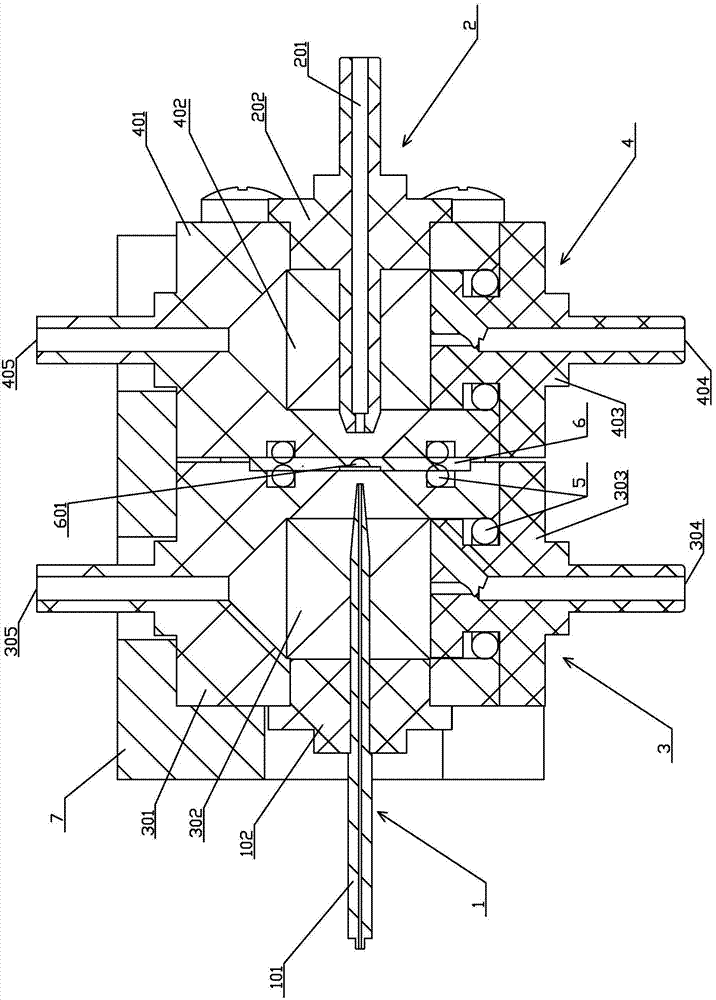
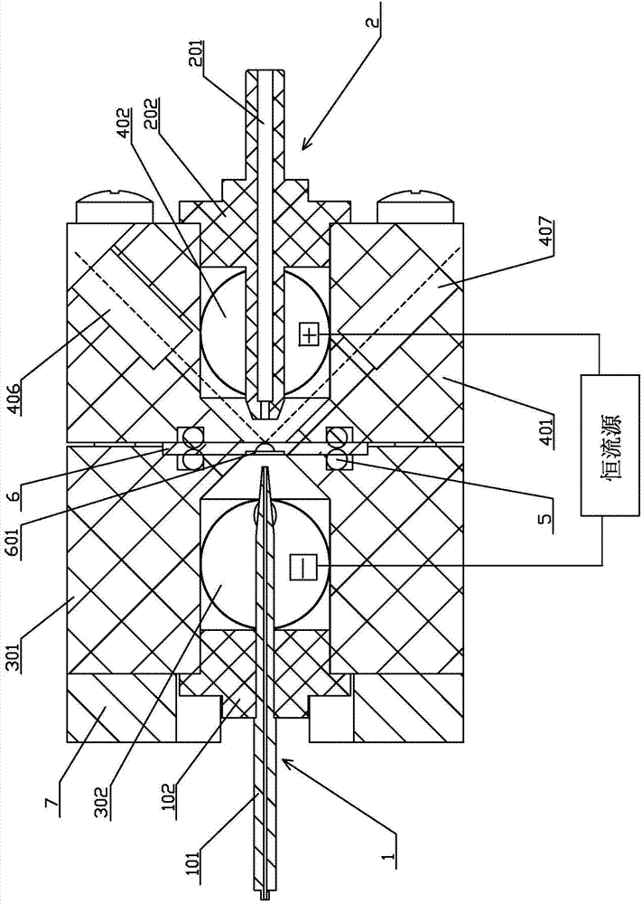
[0021] Such as figure 1 and 2 As shown, the sheath flow impedance and optical synchronous counting device according to the present invention includes a sample needle mounting part 1, a capture tube mounting part 2, a front cell housing 3 and a rear cell housing 4, which are formed on the front cell housing 3 There is a front pool cavity 302, and a rear pool cavity 402 is formed on the back pool shell 4. A gem piece mounting plate 6 is arranged between the front pool shell 3 and the back pool shell 4, and a counting hole 601 is arranged on it. The front pool cavity 302 and the back pool cavity 402 are communicated through the counting hole 601, between the gem piece mounting plate 6 and the front pool shell 3, and between the gem piece mounting plate 6 and the back pool shell 4 are provided with Sealing ring 5; the sample needle installation part 1 is detachably fixed on the front tank housing 3 to seal the front tank cavity 302, and the capture tube installation part 2 is det...


PUM


Abstract

The invention discloses a sheath flow impedance and optical synchronous counting device which comprises a sample needle mounting part, a capture tube mounting part, a front pool shell and a rear pool shell, wherein a front pool inner cavity is formed in the front pool shell; a rear pool inner cavity is formed in the rear pool shell; the front pool inner cavity is communicated with the rear pool inner cavity through a counting hole; the sample needle mounting part is fixed on the front pool shell to seal the front pool inner cavity; the capture tube mounting part is fixed on the rear pool shell to seal the rear pool inner cavity; a laser incidence window and a laser scattering window are formed in the rear pool shell; an axial extension line of the laser incidence window and an axial extension line of the laser scattering window are intersected on the counting hole and form an included angle of about 90 degrees or about 135 degrees. The counting device disclosed by the invention can acquire impedance test data and laser scattering test data of a single cell at the same time when being linked with a system.

Description

technical field [0001] The invention relates to the technical field of medical instruments, in particular to a sheath flow impedance and optical synchronous counting device. Background technique [0002] The counting device is a key component in a hematology analyzer. The existing counting methods commonly used are the electrical impedance method and the laser scattering method. Among them, the working principle of the electrical impedance method is to place a micropore in the liquid to be measured, and add electrodes with a certain voltage to both ends of the micropore. When the liquid When the particles in the micropore pass through the micropore, the resistance between the electrodes will change instantaneously, thus generating an electric pulse. The number of particles can be obtained by analyzing and processing this electric pulse. The size of the pulse amplitude indicates the size of the particle volume. Different types of cells can be distinguished by selecting the m...

Claims


Application Information

Patent Timeline
Patent Type & Authority Applications(China)
IPC IPC(8): G01N15/12G01N15/14
Inventor 唐雪辉
Owner URIT MEDICAL ELECTRONICS CO LTD
Why Eureka
Try Eureka