
A mems piezoresistive accelerometer

An accelerometer and piezoresistive technology, applied in the field of MEMS sensors, can solve problems such as high inter-axis coupling, sensitivity difference, and complex structure, and achieve the effects of reducing device volume, high sensitivity, and improving sensitivity

Inactive Publication Date: 2016-03-02
DALIAN UNIV OF TECH
View PDF5 Cites 2 Cited by
  • Summary
  • Abstract
  • Description
  • Claims
  • Application Information

AI Technical Summary

Problems solved by technology

[0005] The purpose of the present invention is to provide a MEMS piezoresistive accelerometer in order to solve the technical problems of the existing piezoresistive triaxial accelerometers with large volume, complex structure, high coupling degree between axes and large sensitivity difference between different axes. Accelerometer

Method used


Image

  • A mems piezoresistive accelerometer
  • A mems piezoresistive accelerometer
  • A mems piezoresistive accelerometer

Examples


Embodiment 1

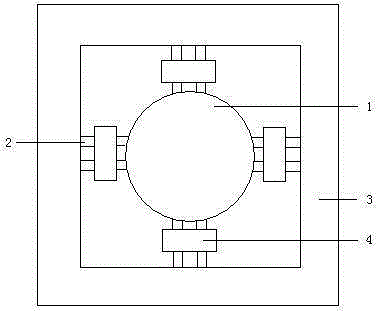
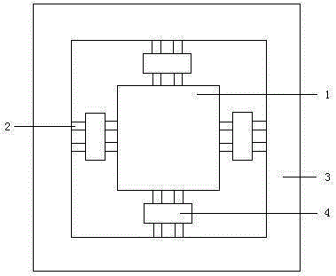
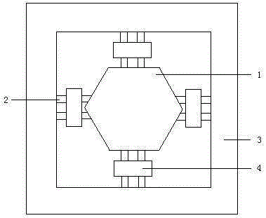
[0030] refer to Figure 4-5, in this embodiment, the main mass 1 adopts a square shape that is easy to process, and two elastic beams 2 are respectively arranged on the four directions of the sides of the square, and the two elastic beams 2 on each side are provided with support The mass block 4 connects the two elastic beams 2; the middle part of the elastic beam 2 and the connection between the elastic beam 2 and the frame 3 are provided with piezoresistors R1~R24 for sensing inertial forces in different directions, and the elastic The beam 2 is provided with a through hole 6; the material of the substrate and the upper sealing cap 5 is glass, and the main mass 1, the elastic beam 2, the frame 3 and the support mass 4 are made of silicon; the substrate and the upper sealing cap The main mass 1 and the frame 3 connected by the elastic beam 2 are sealed between the two through electrostatic bonding, forming a sandwich structure of glass-silicon-glass. The overall size is 5000...


PUM


Abstract

The invention discloses an MEMS piezoresistive accelerometer. The MEMS piezoresistive accelerometer comprises a substrate, a frame, elastic beams, a main mass block, secondary mass blocks, an upper sealing cap and a plurality of sets of piezoresistors, wherein the main mass block is arranged in the center of the frame through the elastic beams in a supporting suspension mode, the frame is fixed to the upper end of the substrate, the secondary mass blocks are arranged on the elastic beams respectively, a specially-shaped elastic beam structure is formed by the secondary mass blocks and the elastic beams, the piezoresistors are arranged in the middle of the elastic beams and the positions of connection between the elastic beams and the frame respectively, the main mass block and the elastic beams are the same in thickness, the upper sealing cap is fixed to the upper end face of the frame, a groove structure is arranged inside the upper sealing cup, and the main mass block is arranged inside a groove in a suspended mode, and can freely move when sensing inertia force in all the directions. According to the MEMS piezoresistive accelerometer, due to the facts that the structure that the elastic beams and the single main mass block are arranged is adopted, and changes of stress, at different positions, of the specially-shaped elastic beams are reflected when the main mass block senses the inertia force in different directions, the size of a device is effectively reduced, and the MEMS piezoresistive accelerometer has the advantages of being high in sensitivity and natural frequency, good in high-overload resistant capacity and the like.

Description

technical field [0001] The invention relates to the field of MEMS sensors, in particular to a three-axis integrated MEMS piezoresistive accelerometer with special-shaped beams. Background technique [0002] MEMS accelerometers processed with micro-mechanical electronic technology (MEMS) with silicon as the substrate and packaged with silicon-glass bonding technology can be widely used in vibration and shock measurements in the fields of aviation, electronics, automobiles and machinery. With the rise of the micro-mechanical and electronic technology industry, accelerometers are gradually becoming miniaturized and integrated. Because micro-accelerometers using MEMS processing technology have the advantages of small size, light weight, low cost, low power consumption, and easy mass production, they have certain market value and military and civilian prospects. [0003] Common micro-accelerometer products are single-axis, but micro-inertial systems and other applications often ...

Claims


Application Information

Patent Timeline
Patent Type & Authority Patents(China)
IPC IPC(8): G01P15/18G01P15/12
Inventor 刘勐郭吉洪王奇汪家奇
Owner DALIAN UNIV OF TECH
Learn More