Synchronous generator stator winding test bench

A synchronous generator and stator winding technology, which is applied in the direction of measuring electricity, measuring device, measuring electrical variables, etc., can solve the problems of not being applicable to mass production requirements and affecting production efficiency, and achieve the effect of simple and reasonable structure and high detection efficiency.

Active Publication Date: 2016-04-13
GUANGXI YUCHAI MASCH CO LTD
View PDF7 Cites 0 Cited by
  • Summary
  • Abstract
  • Description
  • Claims
  • Application Information

AI Technical Summary

Problems solved by technology

[0004] However, after the stator and rotor are installed in the motor casing, they are inspected. After detecting that there is a problem with the stator winding, the stator and rotor need to be removed. After troubleshooting, they are reinstalled into the motor casing for inspection. Production efficiency, not suitable for mass production requirements

Method used


Image

  • Synchronous generator stator winding test bench
  • Synchronous generator stator winding test bench
  • Synchronous generator stator winding test bench

Examples


Embodiment Construction

[0019] A specific embodiment of the present invention will be described in detail below in conjunction with the accompanying drawings, but it should be understood that the protection scope of the present invention is not limited by the specific embodiment. It should be understood that the "upper", "lower", "left", "right", "front" and "reverse" mentioned in the following embodiments of the present invention are all based on the directions shown in the figures, These words used to limit the direction are only for convenience of description, and do not mean to limit the specific technical solution of the present invention.

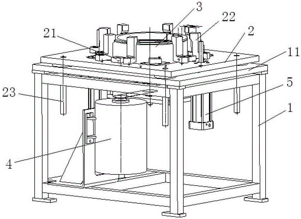
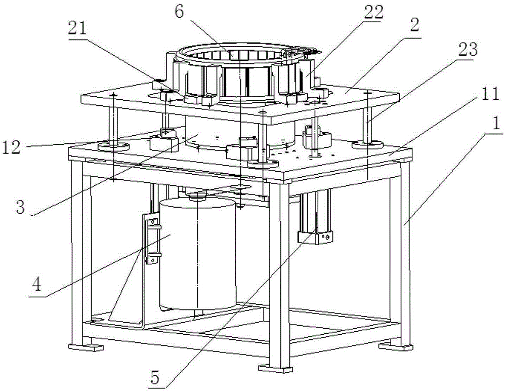
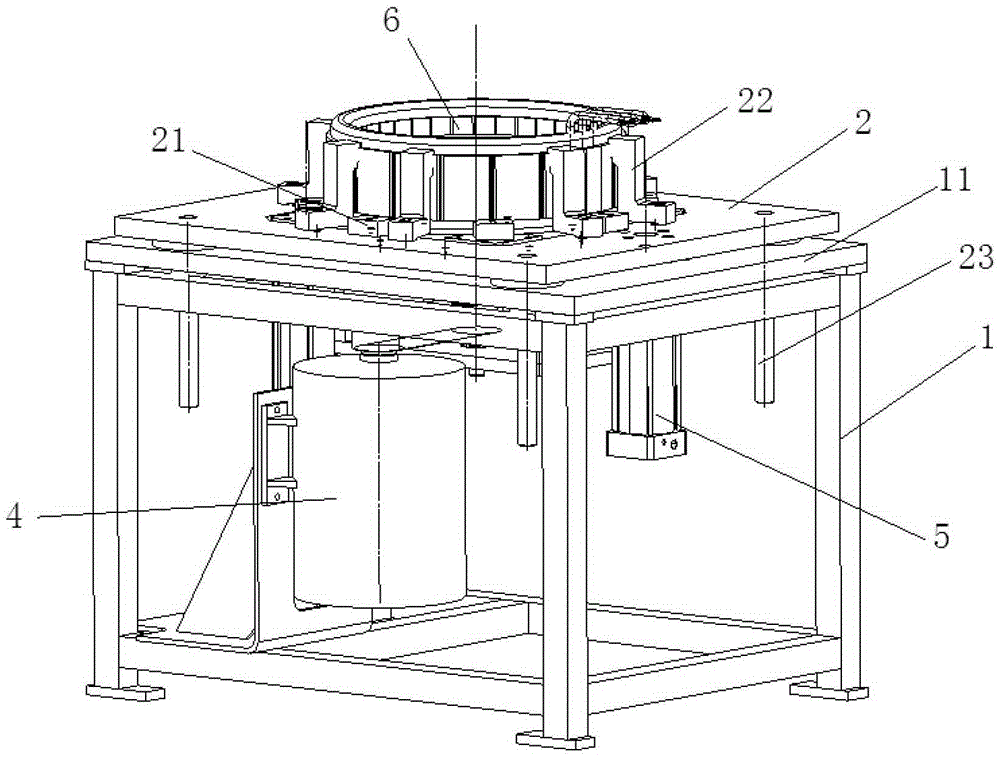
[0020] Such as Figure 1 to Figure 5 As shown, the synchronous generator stator winding test bench of the present invention includes: a test bench frame 1 , a support plate 2 , a tooling rotor 3 , a motor 4 and an air pump 5 . The support plate 2 is driven by the air pump 5 and can be set up and down on the test bench frame 1. The motor 4 drives the tooling...


PUM


Abstract

The invention discloses a synchronous generator stator winding detection rack. The synchronous generator stator winding detection rack comprises a test board machine frame, a supporting plate, a tool rotor, a motor and an air pump, wherein an opening which allows the tool rotor to penetrate through is formed in the center of the supporting plate, the supporting plate is arranged on the top face of the test board machine frame in a mode that the supporting plate can be driven by the air pump to rise and fall, and the tool rotor is vertically arranged on the top face of the test board machine frame in a penetrating mode. In the detection process, a stator which is fixed to the supporting plate and to be detected falls, and the tool rotor is matched with and sleeved with the stator to be detected, and is driven by the motor to rotate in the stator to be detected. The synchronous generator stator winding detection rack is simple and reasonable in structure and high in detection efficiency, the motor stator and the rotor do not need to be installed into a motor shell and then to be detected, and the problem that the assembling efficiency is affected due to the fact that faults are detected to happen to a stator winding and the motor shell needs to be disassembled is solved.

Description

technical field [0001] The invention relates to the field of synchronous generators, in particular to a test bench for stator windings of a synchronous generator. Background technique [0002] The working principle of the synchronous generator is based on the basic principle of the electromotive force induced by the conductor cutting the magnetic force line. Therefore, synchronous generators have magnetic poles that generate magnetic flux lines and conductors that cut magnetic flux lines. There is an excitation winding on the rotor, and when the excitation current is passed through, since the rotor rotates under the action of the original force, an alternating magnetic field will be generated. The three-phase winding of the stator cuts the magnetic force line in turn. It will induce AC electromotive force of equal magnitude and 120° electrical angle difference. [0003] Whether the winding of the three-phase winding inside the stator is qualified is directly related to whe...

Claims


Application Information

Patent Timeline
Patent Type & Authority Patents(China)
IPC IPC(8): G01R1/04G01R31/06
Inventor 卢祥林欧阳石坤卢健林何龙
Owner GUANGXI YUCHAI MASCH CO LTD
Why Eureka
Try Eureka