
Alignment layer group and its manufacturing method, substrate and display device

A manufacturing method and technology of an alignment layer, applied in nonlinear optics, instruments, optics, etc., can solve the problems of easy generation of afterimages and weak anchoring energy, and achieve the effects of improving display quality, suppressing afterimages, improving contrast and display quality

Inactive Publication Date: 2015-12-09
BOE TECH GRP CO LTD
View PDF5 Cites 0 Cited by
  • Summary
  • Abstract
  • Description
  • Claims
  • Application Information

AI Technical Summary

Problems solved by technology

However, optical alignment technology also has disadvantages, its anchoring energy is weak, and it is easy to produce afterimages

Method used


Image

  • Alignment layer group and its manufacturing method, substrate and display device
  • Alignment layer group and its manufacturing method, substrate and display device
  • Alignment layer group and its manufacturing method, substrate and display device

Examples


Embodiment Construction

[0042] The specific implementation manner of the present invention will be described in detail below in conjunction with the accompanying drawings.

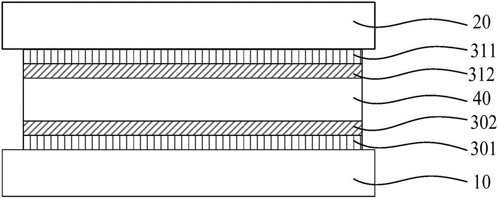
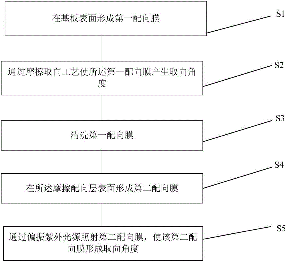
[0043] This embodiment provides an alignment layer group, the alignment layer group includes a rubbed alignment layer and a photo-alignment layer, and the rubbed alignment layer and the photo-alignment layer are sequentially arranged on the upper surface of the substrate along a direction away from the upper surface of the substrate; the rubbed The orientation of the alignment layer is consistent with that of the photo-alignment layer.

[0044] Such as figure 1 As shown, a liquid crystal display panel employs the above-mentioned alignment layer group, and the above-mentioned alignment layer group is respectively arranged on the color filter substrate and the array substrate. Specifically, the display panel includes a color filter substrate 20 , an array substrate 10 disposed opposite to the color filter substrate 20 , and a liqu...


PUM

PropertyMeasurementUnit
wavelengthaaaaaaaaaa

Abstract

The invention relates to the technical field of liquid crystal display, in particular to an alignment layer set, a manufacturing method thereof, a substrate and a display device. The alignment layer set comprises friction alignment layers and smooth alignment layers, wherein the friction alignment layers and the smooth alignment layers are arranged on the upper surface of the substrate in the direction far away from the upper surface of the substrate, and the orientation of the friction alignment layers is identical with that of the smooth alignment layers. According to the alignment layer set, the manufacturing method thereof, the substrate and the display device, a structure of combining the smooth alignment layers and the friction alignment layers is adopted, and the purposes of improving the contrast ratio of liquid crystal panels and simultaneously restraining the generation of residual images to improve the display quality of the liquid crystal panels are achieved by covering detects generated in the friction alignment layers through the smooth alignment layers and by using the anchoring energy of the friction alignment layers for compensating the defect that the smooth alignment layers are poor in anchoring engine.

Description

technical field [0001] The invention relates to the field of display technology, in particular to an alignment layer group, a manufacturing method thereof, a substrate and a display device. Background technique [0002] Liquid crystal displays have been widely used in various electronic products. The main components of the liquid crystal panel include two oppositely arranged substrates, a liquid crystal layer sandwiched between the two substrates; alignment layers are arranged on both sides of the liquid crystal layer, Alignment layers are respectively disposed on opposite inner surfaces of the two substrates. The function of the alignment film is to align the liquid crystal molecules to realize the display function. [0003] Among the existing orientation techniques, the rubbing orientation technique is the most widely used. Rubbing orientation technology can produce better orientation effect, but it also has unavoidable defects. Take the ADS mode (ADvanced SuperDimensio...

Claims


Application Information

Patent Timeline
Patent Type & Authority Patents(China)
IPC IPC(8): G02F1/1337
Inventor 周晓东
Owner BOE TECH GRP CO LTD
Learn More