[0055] The robot can walk automatically in the work area, such as an automatic lawn mower, or an automatic vacuum cleaner, which automatically walks on the lawn or the ground to cut grass or vacuum. Of course, the robot is not limited to automatic lawn mowers and automatic vacuum cleaners, and may also be other types of equipment, such as automatic spraying equipment or automatic monitoring equipment. Through the robot, the unattended operation of various tasks is realized.
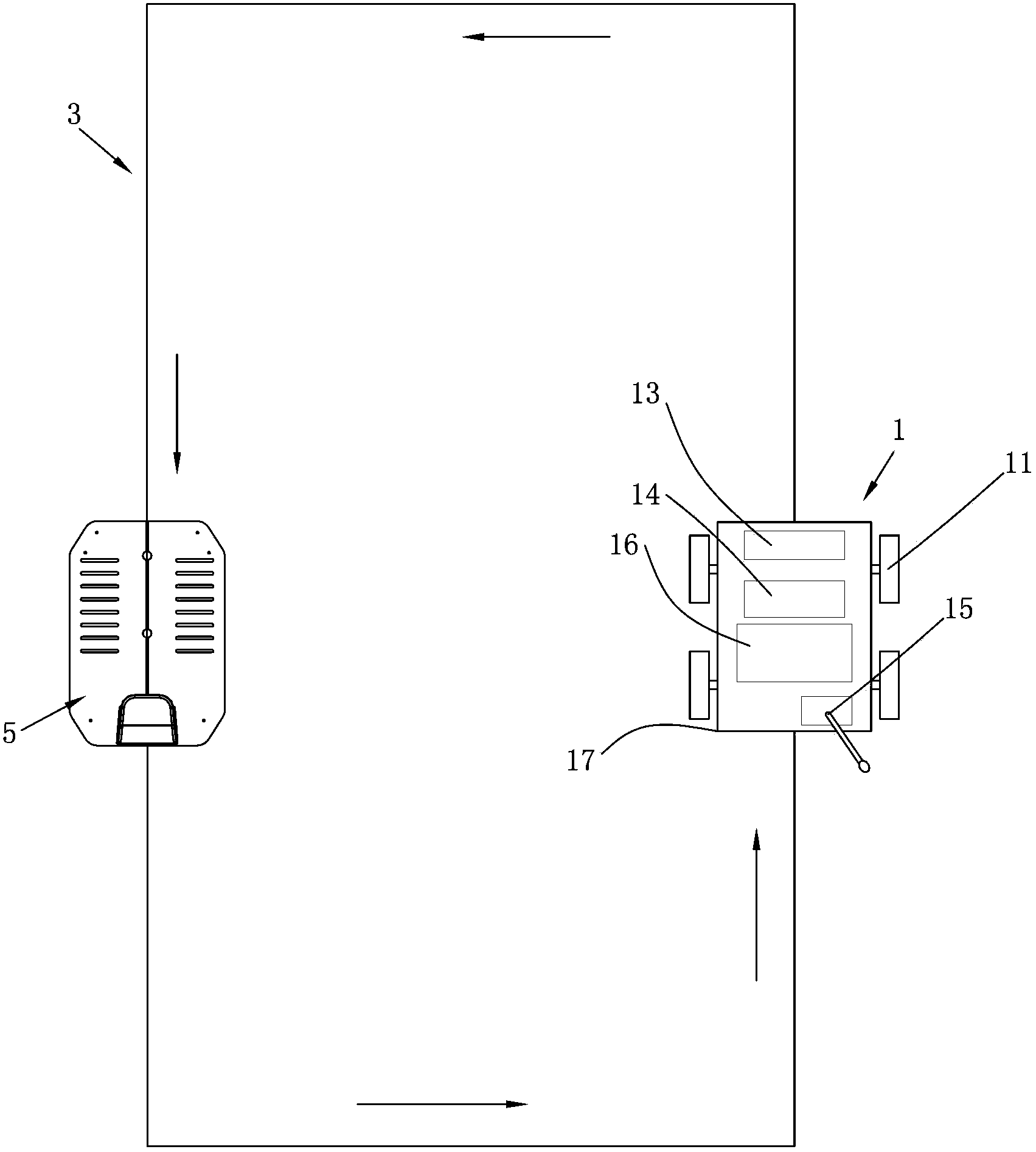
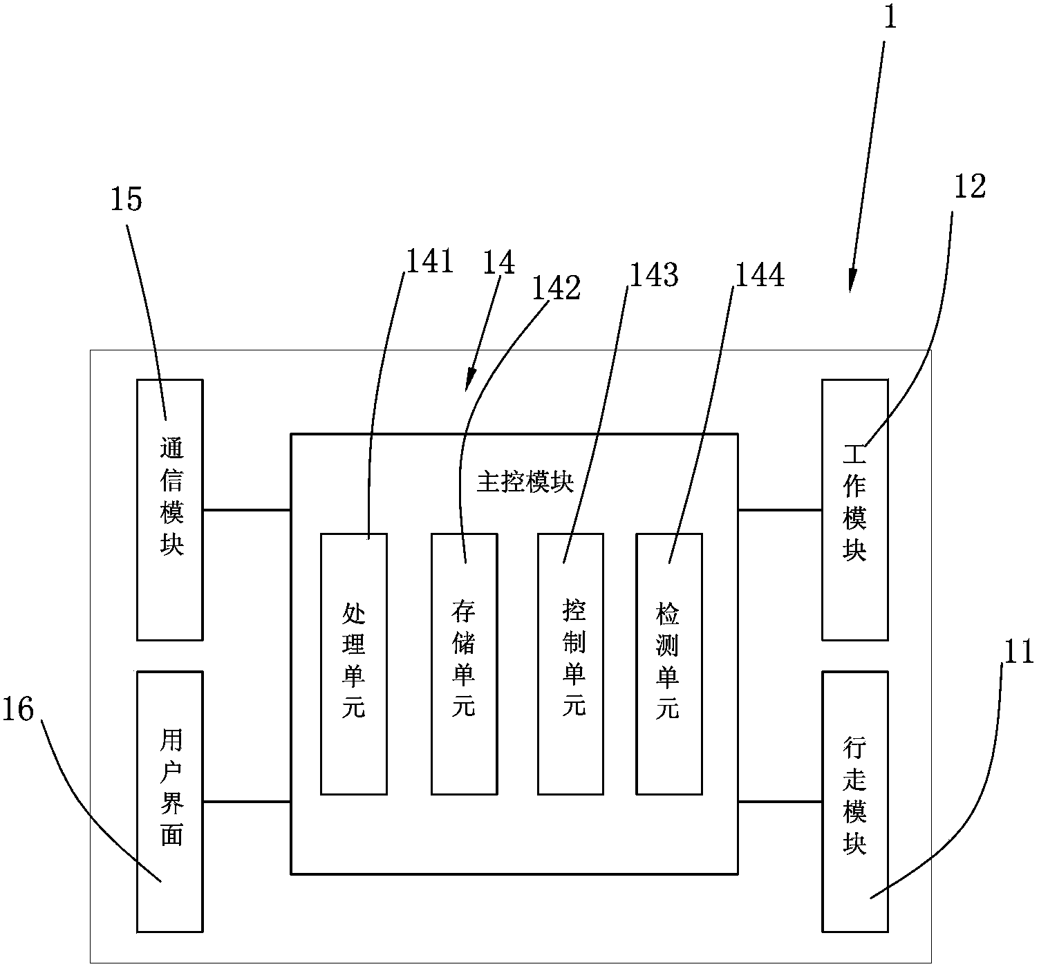
[0056] See Figure 1-Figure 2 , The machine 1 includes a walking module 11, a working module 12, an energy storage module 13, a user interface 16, a communication module 15, a main control module 14, and a housing 17 accommodating the aforementioned modules.
[0057] The working area is a closed area surrounded by a manually set boundary line 3. The boundary line 3 can prevent the machine 1 from leaving the work area; the boundary line 3 can be a wall, a railing, etc.; it can also be an energized wire or other signal generating device, For example, electromagnetic signals or optical signals. There is a docking station 5 in the working area, and the docking station 5 is set on the boundary line 3. When the robot 1 stops working, it stops at the docking station 5 and enters the dormant state; when it needs to start working, it starts from the docking station 5 again and enters Working status. The docking station 5 can generally provide a charging function to charge the energy storage module 13. When the power of the energy storage module 13 is insufficient, the robot 1 returns to the docking station 5 for charging. The docking station 5 can provide guidance and docking for the return of the robot 1. The docking can be guided wirelessly by means of infrared rays or ultrasonic waves, and can also be guided and docked through the boundary line 3.
[0058] The walking module 11 is used to realize the movement of the robot 1 in the working area. The walking module 11 can be walking wheels or mechanical legs. They are usually driven by multiple motors with controllable rotation speed or steering, so as to realize the robot movement. Flexible adjustment of moving speed or moving direction.
[0059] The working module 12 is a module for robots to perform work. The working modules of different robots are different. For example, the working module of an automatic lawn mower includes cutting blades, cutting motors, etc., which are used to perform the cutting work of the automatic lawn mower; The working module of the vacuum cleaner includes a vacuum motor, a vacuum port, a vacuum pipe, a vacuum chamber, a dust collection device and other working parts used to perform the task of vacuuming.
[0060] The energy storage module 13 is usually a rechargeable battery, which provides power for the operation of the automatic lawn mower. It can also be connected to an external power source for charging when the reserve power is lower than a predetermined value; of course, the energy storage module can also be other types of energy supply devices , Such as solar powered devices, gasoline engines or fuel cells, etc.
[0061] The user interface 16 is arranged on the housing 17 where the user can see and operate, such as the top of the robot. The user interface 16 usually includes a display and input keys. The display shows the robot’s menu, operating parameters, etc., and can also be used to inform the user through the display. Display notifications or alarms; input buttons for the user to input instructions to the robot, such as starting and stopping the robot, setting the operating parameters of the robot, etc.; in an alternative embodiment, the user interface 16 can also be set separately from the robot, for example, Remote control for remote control.
[0062] The communication module 15 is used for data information exchange between the robot 1 and the outside world. It can exchange data with the outside world through a wired or wireless connection, and send data information of the robot 1 or receive data information from the outside.
[0063] The main control module 14 includes a processing unit 141, a storage unit 142, a control unit 143, and a detection unit 144. The detection unit 144 is used to detect the operating parameters of the robot 1. The processing unit 141 receives the operating parameters detected by the detection unit 144 or the instructions input by the user interface 16 or the data information received by the communication module 15. After processing, it is controlled by the control unit 143 The walking module 11 and the working module 12 perform walking and working, or send predetermined information through the communication module 15.
[0064] See image 3 , The control method of the robot 1 provided by the present invention includes the following steps:
[0065] Step S 0: Detect operating parameters. When the robot 1 is working, the detection unit 144 detects various operating parameters of the robot 1 at all times.
[0066] Monitoring the operating parameters of the machine 1 includes monitoring the temperature of the robot 1, whether it is raining, the tilt angle of the machine 1, and whether a collision occurs. These operating parameters can be detected by various sensors arranged on the machine 1, and these sensors can be temperature sensors, rain sensors, acceleration sensors, displacement sensors, gravity sensors, and so on. When the aforementioned operating parameters of the robot 1 change, these changes can be detected by the processing unit 141 through the aforementioned sensors.
[0067] The operating parameters of the monitoring machine 1 include various electrical characteristics of the machine 1. These parameters can be detected by the electrical characteristic detection unit provided on the machine 1, such as the current detection unit, the voltage detection unit, and the battery capacity detection unit. When the electrical characteristics of 1 change, these changes can be detected by the processing unit 141 through the electrical characteristic detection unit described above.
[0068] Of course, the detection unit 144 of the machine 1 can also include other types of detection methods. Those skilled in the art can easily imagine that there are some distance sensors, magnetic field sensors, etc., which can also be set on the robot 1 to detect the The operating parameters are not listed here because of space limitations. When the machine 1 detects the operating parameters, it can perform the detection alone or simultaneously detect multiple operating parameters.
[0069] Step S1: Read standard data. The storage unit 142 stores the standard data of various operating parameters of the machine 1. When the processing unit 141 receives the operating parameters detected in step S0, the processing unit 141 reads the standard data of the corresponding operating parameters from the storage unit 142.
[0070] The standard data of the machine 1 is used to define the operating parameter values that are allowed to appear on the machine 1 or the operating parameter values that are not allowed to appear on the machine 1. The standard data can have many forms, which can define the limit values of the operating parameters of the robot 1, such as the maximum and minimum voltages of the energy storage module 13 of the robot 1, the maximum operating current of the machine 1, and so on; It defines whether a certain parameter of the robot 1 is allowed to be detected, for example, the sensor of the machine 1 is not allowed to detect that the machine 1 is tilted to a certain angle or turned over.
[0071] The machine 1 can have a set of standard data of operating parameters. Further, the robot 1 has multiple sets of standard data of operating parameters, corresponding to different working modes.
[0072] When the working mode of 1 is switched, the standard data of the operating parameters are also changed accordingly.
[0073] Step S2: Determine whether an abnormality occurs. The processing unit 141 compares the operating parameters detected by the detection unit 144 with the standard data stored in the storage unit 142. When the detected operating parameters belong to operating parameter values that are not allowed to appear on the robot 1, the processing unit 141 judges the robot 1 If an abnormality occurs, proceed to the next step; otherwise, the processing unit 141 determines that the robot 1 has no abnormality and returns to step S0.
[0074] The processing unit 141 can determine whether the robot 1 is abnormal in a variety of ways: the processing unit 141 can determine according to any one of the operating parameters, such as when the voltage value of the energy storage module 13 is lower than the standard data, or when multiple collisions occur , Or when rain is always detected, or it is detected that a certain motor of the walking module 11 of the robot 1 has no current flowing, etc., it is determined that the robot 1 is abnormal.
[0075] The processing unit 141 can also determine whether multiple operating parameters occur at the same time. For example, when the robot 1 detects that it has been connected to the charging station, but the charging terminal does not always detect the voltage, it determines that the robot 1 is abnormal; for example, when the energy storage is detected. Module 12 is fully charged, but still connected to the charging station, it is judged that the robot 1 is abnormal; for example, when it is detected that the tilt angle of the robot 1 is greater than 40 degrees, if it is detected that the working module 12 is still running, it is judged that the robot 1 is abnormal, etc. Wait.
[0076] The processing unit 141 can also judge according to the sequence in which multiple operating parameters are detected, or judge according to whether the operating parameters appear within the allowed time range, etc. These methods can be determined by the manufacturer or the user according to the robot 1 The conditions of use or personal preferences are set, so I won’t list them all here.
[0077] Of course, the various judgment methods described above can be used alone or at the same time, but as long as any one of the judgment methods judges that an abnormality has occurred, it can be considered that the robot 1 is abnormal.
[0078] Step S3: Generate a fault code. When the operating parameters are abnormal, the robot 1 uses the fault code to indicate the details of the abnormal information in order to facilitate the recording, display or transmission of the abnormal information. The storage unit 142 stores fault codes corresponding to various abnormal conditions or standard data, which are used to represent the details of the abnormality. The fault code is usually a set of numbers. For the same kind of robot 1 or the same manufacturer's robot 1, these digital codes are usually universal. Of course, the fault code can also be represented in other forms, such as letters, combinations of letters and numbers, and so on. When the processing unit 141 determines that an abnormality has occurred, it reads the fault code corresponding to the abnormal situation from the storage unit 142.
[0079] Step S4: Detect the communication connection. See also Figure 4 The communication module 15 includes a wireless network card. When the robot 1 is within the coverage of a wireless router 18 or wireless AP (wireless access node) connected to the Internet, the wireless network card can access the Internet through WIFI based on wireless local area network technology. When the communication module 15 detects the network connection, it proceeds to the next step, otherwise, returns to step S4, and the robot 1 continues to detect the communication connection while it is moving.
[0080] Further, the communication module 15 may also include a mobile communication network access unit such as GSM/CDMA. See also Figure 5 , The communication module 15 can send text or digital information through the GSM/CDMA network within the coverage of the base station 19 of the mobile communication network, and it can also access the Internet through the GSM/CDMA network. Compared with wireless local area network technology, this communication connection The connection distance is longer, and the robot 1 can move and work freely in a larger range.
[0081] Step S5: Send the fault code. When the communication connection is normal, the communication module 15 sends the fault code generated in step S3 to a preset network address, and the preset network address corresponds to the address of the fault analysis unit of the robot 1, such as the maintenance or repair of the robot 1. E-mail address or GSM/CDMA network terminal of the after-sales service department. Further, the preset network address can be set by the user, so that the fault code can always be sent to the latest network address.
[0082] Step S6: Receive the fault code. The e-mail or GSM/CDMA network terminal of the maintenance after-sales service department of the robot 1 receives the fault code and stores it.
[0083] Step S7: Decoding the fault code. The maintenance and after-sales service department of Robot 1 stores the corresponding list of fault codes and various abnormal conditions or standard data. After receiving the fault code, the fault code is restored to the operating parameters through the corresponding coding principle stored in Robot 1. Details of the exception.
[0084] Step S8: Analysis of the cause of the failure. The maintenance and after-sales service department of Robot 1 analyzes the cause of the abnormality of the operating parameters. Preferably, the cause of the abnormality of the operating parameters can be automatically performed by the database robot. The database of the after-sales service department stores various operating parameter abnormalities. The cause of occurrence, and the cause of the failure corresponding to the value of different abnormal data in the same operating parameter, the database robot can automatically find the cause or component of the failure according to the value of the abnormal data in the abnormal information. Of course, the analysis of the abnormal cause can also be done manually.
[0085] Step S9: Generate fault solutions. The maintenance and after-sales service department of the robot 1 will provide corresponding solutions according to the cause or component of the fault. The solutions can be generated automatically through the database robot or given by the staff of the after-sales service department. Fault solutions are generally detailed and easy for users to understand and execute text. When the cause or component of the fault cannot be determined, or cannot be easily solved, the database robot or staff will suggest that the user bring the robot 1 back to the after-sales service department for detailed inspection.
[0086] Step S10: Send fault resolution information. The after-sales service department of the robot 1 sends the troubleshooting information to the predetermined receiving address through the Internet or the mobile communication network, in the form of email or short message. The receiving address is usually set by the user when purchasing the robot 1 or registering the robot 1 with the manufacturer. The receiving address can be an email account or a mobile communication account.
[0087] Step S11: receiving fault resolution information. The user's preset computer or mobile phone and other network connection terminals receive troubleshooting information. Further, the network connection terminal usually has a display component for displaying fault resolution information; the network connection terminal may also have a sounder to remind the user that the fault resolution information is received.
[0088] Step S12: Resolve the fault. The user operates or repairs the robot 1 according to the received troubleshooting information, thereby solving the malfunction of the robot 1.
[0089] Through the robot control method provided by the present invention, people can know whether the robot has a fault in time, and when a fault occurs, the fault can also be resolved in time through the received fault resolution information, thereby ensuring the progress of the work plan without requiring every Every time, the robot is sent to the after-sales service department designated by the manufacturer for inspection and maintenance, which brings convenience to users.
[0090] See Image 6 , Is the control method of the robot 1 provided by the second embodiment of the present invention. Compared with the first embodiment, the difference lies in the way the robot 1 sends the fault code. When the robot 1 is abnormal, the following steps are executed:
[0091] Step S24: Return to the stop. When the robot 1 judges that an abnormality has occurred, it starts to return to the docking station. The return of the robot 1 can be guided in a wired or wireless manner. See also figure 1 The docking station 5 is set on the boundary line 3. When the robot 1 judges that an abnormality occurs, the robot 1 searches for the nearest boundary line 3 through the detection unit 144. When the detection unit 144 detects that the robot 1 is already on the boundary line 3, it starts to move along Follow the boundary line 3 figure 1 Move in the direction of the arrow shown in the figure until you return to the stop.
[0092] The robot 1 returning to the docking station 5 can also be guided in a wireless manner. For example, an infrared emitting device is arranged on the docking station 5, and the detection unit 144 of the robot 1 includes an infrared receiving device, and the returning is guided by infrared. In addition, it can also be guided by ultrasonic or magnetic field induction.
[0093] Step S25: Detect the communication connection. See also Figure 7 , The docking station 5 includes a first connecting component 51 and a second connecting component 52. The first connection component 51 is adapted to the communication module 15 of the robot 1 and is used for information exchange between the docking station 5 and the robot 1; the second connection component 52 is connected to the Internet and is used for communication between the docking station 5 and the Internet. Information exchange.
[0094] Such as Figure 7 As shown, the communication mode between the first connection assembly 51 and the communication module 15 is wired communication. The housing 17 of the robot 1 is provided with a first terminal 171. When the robot 1 stops at the docking station 5, the first terminal 171 communicates with The first connection component 51 is electrically connected, and the first terminal 171 can perform data transmission with the first connection component 51 through serial data transmission or parallel data transmission, such as a common USB interface.
[0095] The communication between the first connection component 51 and the communication module 15 may also adopt a wireless communication method, such as infrared, Bluetooth, or wireless local area network. According to different communication methods, the first connection component 51 and the communication module 15 have corresponding infrared emission and Receiving components, Bluetooth components or wireless network card components, etc., the above components perform data transmission through the corresponding communication protocol.
[0096] Of course, the docking station 5 can also be connected to a computer through the second connecting component 52 and then access the Internet through the computer. Compared with the docking station 5 directly connecting to the Internet, the size and manufacturing cost of the docking station 5 can be reduced.
[0097] In the robot control method provided by the second embodiment of the present invention, the communication connection is more stable and reliable. At the same time, when the robot fails, it will not randomly stop at the location where the failure occurred, but will automatically return to the docking station to wait for maintenance. In the case of a large area, when the robot fails, there is no need for the user to find the failed robot, which brings convenience to the user.
[0098] See Figure 8 , Which is the control method of the robot 1 provided by the third embodiment of the present invention. Compared with the first embodiment or the second embodiment, the difference lies in the way of receiving the fault solving information and the way of solving the fault. After the failure analysis unit analyzes the cause of the failure, perform the following steps:
[0099] Step S39: Generate a fault solution. The after-sales service department of the robot 1 will provide corresponding solutions according to the cause or component of the fault. The solutions can be generated automatically through the database robot or given by the staff of the after-sales service department. Different from the first embodiment and the second embodiment of the present invention, the fault solution is an execution code or program that the robot 1 can recognize.
[0100] Step S310: Send fault resolution information. The after-sales service department of the robot 1 sends the troubleshooting information to the robot 1 that issued the corresponding fault code via the Internet or mobile communication network.
[0101] Step S311: Receive fault resolution information. The robot 1 receives the fault resolution information through the communication module 15 and stores the fault resolution information in the storage unit 142.
[0102] Step S312: Determine whether the reception is completed. When the communication module 15 does not receive the information again within the predetermined time period, the processing unit 141 determines that the failure resolution information has been received. Those skilled in the art can imagine that there are many ways to make judgments, such as adding termination information to the fault resolution information. When the processing unit 141 receives the termination information, it is determined that the fault resolution information has been received. Otherwise, continue to receive.
[0103] Step S313: Resolve the fault. When the robot 1 judges that the failure resolution information has been received, it reads the failure resolution information from the storage unit 142. The troubleshooting information is a complete program that guides the robot 1 to run. This program is written for the situation that the robot 1 is currently in and causes the failure. It can treat the actual environment of the robot 1 differently from the program currently executed by the robot 1. , So that the operating parameters of the robot 1 return to normal. The processing unit 141 interrupts the currently executing program, executes the program contained in the troubleshooting information, and helps the robot 1 to escape from the current situation that caused the failure. For example, when the robot 1 cannot leave the obstacle after executing the original program, the troubleshooting information can be targeted Obstacle information provided in the fault information, formulate a special walking path, leave the obstacle, etc.
[0104] In an alternative embodiment, the fault resolution information is a modification to the existing program of the robot 1. The processing unit 141 replaces the parameters of the program being executed by the robot 1 with the corresponding parameters in the fault resolution information to adapt to the current program of the robot 1. In an alternative embodiment, the fault resolution information is an execution code that can be recognized by the robot 1, and the storage unit 142 stores an execution code corresponding to the identification code. The program instructs the robot to complete pre-set actions, such as moving in a certain direction, returning to docking station 5 or restarting robot 1 and so on. When the robot 1 receives the execution code, the processing unit 141 reads from the memory 142 and executes the action corresponding to the identification code, helping the robot 1 to escape from the current situation causing the failure.
[0105] The method for controlling the robot 1 provided by the third embodiment of the present invention enables the robot 1 to recompile or restart the robot through its program, and repair faults on its own, thereby realizing unattended operation and bringing convenience to users.
[0106] Those skilled in the art can imagine that in the robot 1 control method provided in the embodiment of the present invention, some steps can be switched in order or occur at the same time. For example, the robot 1 generates a fault code and then returns to stop 5 or returns to stop 5 and then The generation of the fault code will not affect the effect of the present invention; of course, it is also possible for the robot 1 to generate the fault code and return to the docking station 5 at the same time, which does not affect the essence of the present invention.
[0107] In the control method of the robot 1 provided by the present invention, when a robot malfunctions, the user can know in time, and can remotely learn the troubleshooting method, and eliminate the malfunction through the received troubleshooting information, thereby ensuring the progress of the work plan. There is no need to send it to the maintenance after-sales service department for inspection and maintenance every time, which brings convenience to users.
[0108] Those skilled in the art can imagine that the present invention can also have other implementations, but as long as the technical essence adopted is the same or similar to the present invention, or any changes and replacements that are easy to think about based on the present invention are all in Within the protection scope of the present invention.