RFID entry-and-exit recognition system and in-and-out recognition method thereof

An identification system and identification method technology, applied in the field of entry and exit state identification systems, can solve the problems of reduced wiring, high cost, and complicated wiring, and achieve the effects of improved accuracy and reliability, simple structure, and convenient installation

Active Publication Date: 2014-02-12
LIERDA SCI & TECH GRP
View PDF8 Cites 31 Cited by
  • Summary
  • Abstract
  • Description
  • Claims
  • Application Information

AI Technical Summary

Problems solved by technology

[0004] The present invention mainly solves the technical problems that the original radio frequency identification system has many equipments, high cost, complicated and cumbersome wiring, and there are limitations in the use occasions, and the identification reliability is not high; it provides an RFID entry and exit identif...

Method used


Image

  • RFID entry-and-exit recognition system and in-and-out recognition method thereof
  • RFID entry-and-exit recognition system and in-and-out recognition method thereof
  • RFID entry-and-exit recognition system and in-and-out recognition method thereof

Examples


Embodiment 1

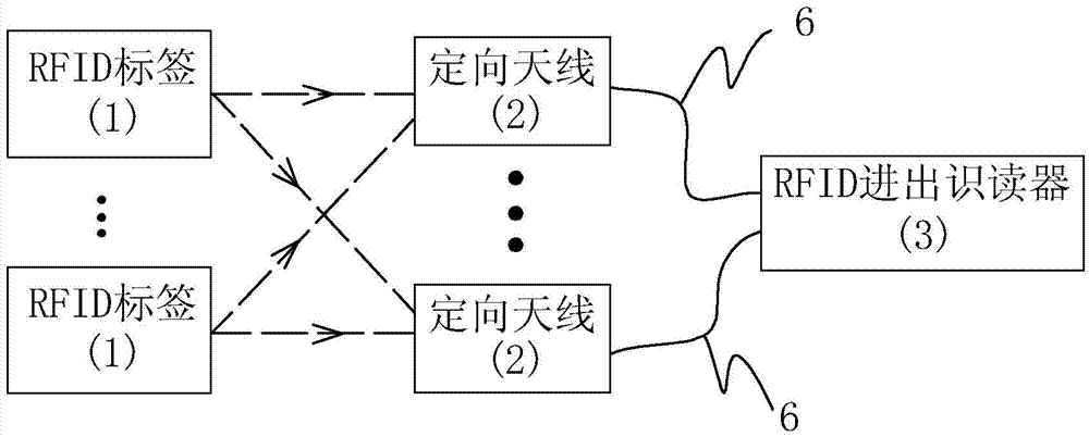
[0033] Embodiment 1: the RFID entry and exit identification system of this embodiment, such as figure 1 As shown, it includes many RFID tags 1, two directional antennas 2 and an RFID entry and exit reader 3. The RFID tag 1 is located on the person or object that needs to be identified for entry and exit, and the two directional antennas 2 are installed on the entry and exit channel 4. One of the directional antennas 2 is installed on the inner side 41 of the access passage, and the other directional antenna 2 is installed on the outer side 42 of the access passage, such as Figure 4 As shown, the directional antenna 2 is inclined to the access channel 4, the directional antenna 2 positioned at the inner side 41 of the access channel faces the inner side 41 of the access channel, the directional antenna 2 positioned at the outer side 42 of the access channel faces the outer side 42 of the access channel, and the two directional antennas 2 are arranged in the direction of the acc...

Embodiment 2

[0043] Embodiment 2: the RFID entry and exit identification system of this embodiment, such as Figure 7As shown, there are four directional antennas 2, and the four directional antennas 2 are arranged and installed along the length direction of the access passage 4, wherein two directional antennas 2 are installed on the inner side 41 of the access passage, and the other two directional antennas 2 are installed on the outer side 42 of the access passage The directional antenna 2 is arranged obliquely at the access passage 4, and the four directional antennas 2 are symmetrical to each other with the installation position of the door 5 on the access passage 4 as a symmetrical axis, and the directional antenna 2 positioned at the inner side 41 of the access passage and close to the door 5 faces the inner side 41 of the access passage, Another directional antenna 2 positioned at the inner side 41 of the access passage and away from the door 5 is towards the outer side 42 of the ac...

Embodiment 3

[0049] Embodiment 3: the RFID entry and exit identification system of this embodiment, such as Figure 8 As shown, there are four directional antennas 2, wherein two directional antennas 2 are installed on the inner side 41 of the access passage, and the other two directional antennas 2 are installed on the outer side 42 of the access passage. The width direction of passage 4 is arranged and installed, and is respectively located on the left side and the right side of the passageway, and the directional antenna 2 is inclined to the passageway 4. The two directional antennas 2 on the inner side 41 of the access passage face the inner side 41 of the passageway, and the two directional antennas 2 located on the outer side 42 of the passageway face the outer side 42 of the passageway. All the other structures are with embodiment 1.

[0050] The entry and exit identification method of the above-mentioned RFID entry and exit identification system is the same as that in Embodiment 2...


PUM


Abstract

The invention relates to an RFID in-and-out recognition system and an in-and-out recognition method thereof. The RFID in-and-out recognition system comprises an RFID tag, directional antennas and an RFID in-and-out recognizer, the number of the directional antennas is two or the multiple of the two, one half of the antennas are slantly installed inside an in-and-out channel, the other half of the antennas are slantly installed outside the in-and-out channel, the directional antennas inside and outside the in-and-out channel are mutually symmetric by using a door as the symmetric axis, and the directional antennas are connected with the RFID in-and-out recognizer through feeder lines. The in-and-out recognition method comprises the steps of judging that the RFID tag enters or leaves the recognition region from the exterior of the door or the interior of the door, therefore, judging the situation of door entry and exit conditions of the RFID tag, and therefore achieving the recognition of entry and exit of the human body or an object with the RFID tag. According to the system, wiring is easy, maintenance is convenient, the installation distance is not limited, and the recognition accuracy is high.

Description

technical field [0001] The invention relates to an entry and exit state identification system, in particular to an RFID entry and exit identification system and an entry and exit identification method thereof. Background technique [0002] RFID (Radio Frequency IDentification) is radio frequency identification, also known as electronic tags and radio frequency identification. It is a communication technology that can identify specific targets through radio signals and read and write related data without the need for mechanical or optical contact. Through RFID technology, high-speed moving objects can be identified and multiple electronic tags can be identified at the same time, and the operation is fast and convenient. RFID systems generally include electronic tags, readers and antennas. The electronic tag is composed of a coupling element and a chip. Each tag has a unique electronic code and is attached to the object to identify the target object; the reader reads (someti...

Claims


Application Information

Patent Timeline
IPC IPC(8): G06K7/00
Inventor 钟柳波郑旭
Owner LIERDA SCI & TECH GRP
Why Eureka
Try Eureka