

Adjusting device for drawer slide rail system
A technology of adjusting device and drawer, which is applied to drawers, furniture parts, household appliances, etc., can solve the problems of difficult installation and positioning, complex structure, etc., and achieve the effect of smooth opening and closing process, high connection compactness, and increased strength.
- Summary
- Abstract
- Description
- Claims
- Application Information
AI Technical Summary
Problems solved by technology
Method used
Image

Examples
no. 1 example
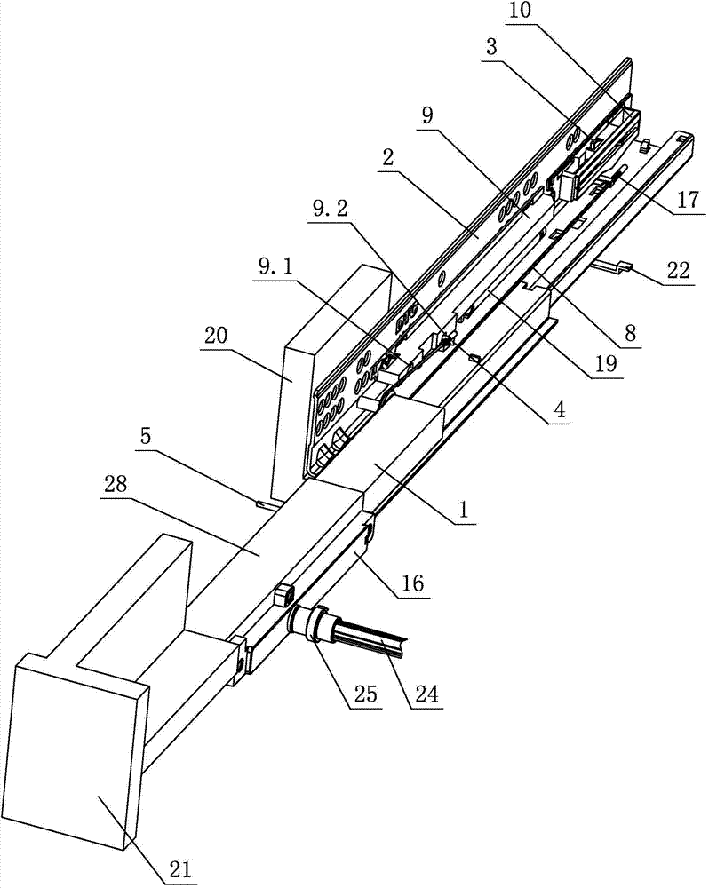
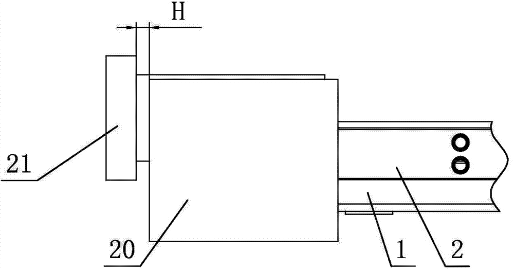
[0024] see figure 1 - Figure 8 , the adjustment device of the drawer slide rail system, including two sets of slide rail assemblies arranged on the left and right cabinet side panels 20, the slide rail assembly is provided with a drawer, and the drawer is at least composed of a bottom plate and a front panel 21, and is characterized in that the slide rail The assembly is at least composed of a moving slide rail 1 and a fixed slide rail 2. The left and right moving slide rail 1 or the fixed slide rail 2 is provided with an adjustment device, and the drawer is synchronously adjusted by the adjustment device on it or the movable slide rail 1 or the fixed slide rail. The depth position of the damping device of the rail 2 and the synchronous rebounding device realizes the adjustment of the gap position between the front panel 21 and the side panel 20 of the cabinet; at least when the drawer is closed, the elastic stopper 7 arranged on the synchronous rebounding device is automati...
no. 2 example
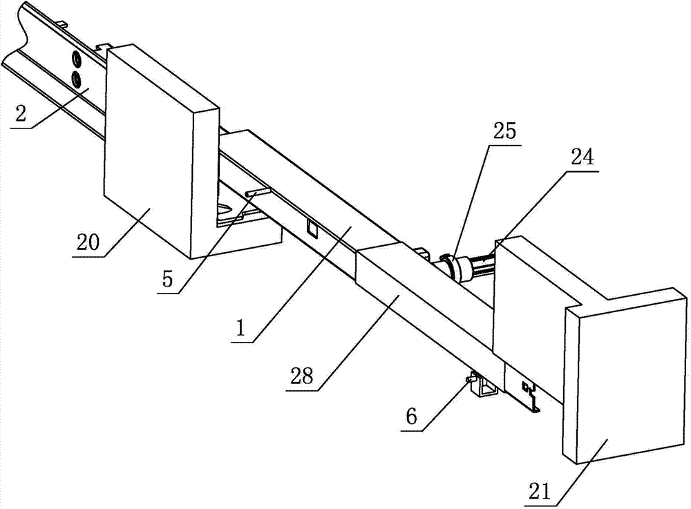
[0039] see Figure 9 , Figure 10 The adjustment device of this drawer slide rail system is different from the first implementation in that: the adjustment device is arranged on the fixed slide rail 2, the adjustment device at least includes an adjustment seat 28 and an adjustment member 29, and the adjustment seat 28 is provided with a function part dial Block 22, and at least act on the stopper 14.2 of the moving part 14 of the synchronous rebounding device when the drawer is closed, so as to realize the sliding of the moving part 14 on the sliding cover 16 and act on the elastic stopper 7; the damping device Set on the adjusting seat 28 through the buckle 9.3 set on the cage 9 . The user adjusts the adjusting member 29 to make the adjusting seat 28 shift, so that the position of the shifting block 22 and the damping device changes, and the stroke when the drawer is closed is also changed. The ultimate purpose of this change is to realize the adjustment of the front panel 2...
PUM
 Abstract
Description
Claims
Application Information