Magnetic trap for capturing magnetic impurities in high-temperature liquid metal coolant

A liquid metal cooling and magnetic impurity technology, applied in the direction of high-gradient magnetic separators, can solve the problems of wire mesh corrosion, coolant introduction, and inability to flow through the sorting space, so as to avoid erosion and corrosion and improve efficiency.

Inactive Publication Date: 2014-02-19
HEFEI UNIV OF TECH
View PDF6 Cites 5 Cited by
  • Summary
  • Abstract
  • Description
  • Claims
  • Application Information

AI Technical Summary

Problems solved by technology

However, when the method of increasing the magnetic field gradient by setting the wire mesh in the sorting space is applied to the purification of the high-temperature liquid metal coolant, there will be two main problems: the one is that the high-temperature liquid metal coolant will flow through the wire mesh. It has a strong erosion and corrosion effect on the wire mesh, thereby introducing additional impurities into the coolant, and even the entire wire mesh may be completely corroded; second, the high-temperature liquid metal coolant has a high density and a high viscosity in the low-temperature operating section. Relatively poor, when the wire mesh filters impurities and the mesh holes are partially or completely blocked, it may cause the high-temperature liquid metal coolant to fail to flow through the sorting space, thus increasing the frequency of replacing the magnetic trap sorting space
[0005] So far, there has been no public report of a device that can more effectively purify high-temperature liquid metal coolant

Method used


Image

  • Magnetic trap for capturing magnetic impurities in high-temperature liquid metal coolant
  • Magnetic trap for capturing magnetic impurities in high-temperature liquid metal coolant
  • Magnetic trap for capturing magnetic impurities in high-temperature liquid metal coolant

Examples


Embodiment Construction

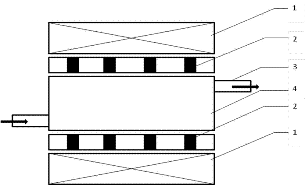
[0024] see figure 1 , the structural form of the magnetic trap used to capture the magnetic impurities in the high-temperature liquid metal coolant in this embodiment is: the non-magnetic stainless steel box body 4 with the flange interface 3 at both ends is connected in series through its flange interface 3 at high temperature In the circulation circuit of the liquid metal coolant, a ferromagnetic cylinder 2 is arranged on one side or two symmetrical sides of the nonmagnetic stainless steel box 4, and the axis of the ferromagnetic cylinder 2 is connected to the axis of the nonmagnetic stainless steel box 4. The side plate is vertical so that it is perpendicular to the flow direction of the high-temperature liquid metal coolant in the non-magnetic stainless steel box 4; a magnetic field source system 1 is arranged on the outside of the ferromagnetic cylinder 2, and the magnetic field source system 1 passes through the iron The magnetic cylinder 2 forms a magnetic impurity sepa...


PUM


Abstract

The invention discloses a magnetic trap for capturing magnetic impurities in a high-temperature liquid metal coolant. The magnetic trap is characterized in that a no-magnetic-conductivity stainless steel box body with flange connection openings formed in the two ends is connected in series to a circulation loop of the high-temperature liquid metal coolant through the flange connection openings; ferromagnetic column bodies are arranged on one side or two symmetric sides of the no-magnetic-conductivity stainless steel box body; the axis of each ferromagnetic column body is perpendicular to a side plate of the no-magnetic-conductivity stainless steel box, so that the ferromagnetic column bodies can be perpendicular to the flowing direction of the high-temperature liquid metal coolant in the no-magnetic-conductivity stainless steel box; a magnetic field source system is arranged on the outer sides of the ferromagnetic column bodies and forms a magnetic impurity separation space with set magnetic field intensity and a set magnetic field gradient in the no-magnetic-conductivity stainless steel box body through the ferromagnetic column bodies. The magnetic trap is used for realizing on-line continuous capturing of iron-based impurities in the liquid metal coolant and can effectively purify the high-temperature liquid metal coolant.

Description

technical field [0001] The invention relates to a magnetic trap device for capturing magnetic impurities in high-temperature liquid metal coolant. Background technique [0002] High-temperature liquid metals, such as liquid lead-bismuth alloys, are very potential coolants in accelerator-driven subcritical reactors (ADS), which have excellent thermophysical and chemical properties. However, during the operation of the reactor, due to the corrosion of high-temperature liquid metal on stainless steel pipes and the reaction of high-temperature liquid metal with oxygen, Fe, Ni and related oxide impurities are continuously produced in this coolant. The generation of impurities will not only reduce the thermal conductivity of the high-temperature liquid metal coolant, but more seriously, in the operating section with a lower temperature, these impurities may precipitate and accumulate, which may cause blockage of the reactor core cooling circulation pipeline, resulting in serious c...

Claims


Application Information

Patent Timeline
Patent Type & Authority Applications(China)
IPC IPC(8): B03C1/025B03C1/031
Inventor 李强吕科锋王艳青刘少军黄群英
Owner HEFEI UNIV OF TECH
Why Eureka
Try Eureka