Engine suspension cushion

An engine mount and cushion technology, which is used in power plants, jet propulsion devices, internal combustion propulsion devices, etc., can solve the problems of reduced strength of engine mount cushions, affecting reliability, poor decoupling effect, etc., to meet NVH requirements. Performance requirements, reduced vehicle weight, and the effect of easy assembly

Active Publication Date: 2014-02-19
CHONGQING CHANGAN AUTOMOBILE CO LTD
View PDF6 Cites 6 Cited by
  • Summary
  • Abstract
  • Description
  • Claims
  • Application Information

AI Technical Summary

Problems solved by technology

In this case, the common method is to arrange an engine suspension cushion directly above the transmission, one end of the engine suspension cushion is connected to the transmission, and the other end of the engine suspension cushion is connected to the frame beam to fix the power. assembly, but there are the following problems: 1. Since the engine suspension cushion is arranged directly above, there must be a certain motion envelope during the up and down movement of the vehicle
In order to avoid the collision of the engine mount cushion with the transmission and the frame beam, it is necessary to require the metal skeleton of the engine mount cushion itself to be relatively long in the Z direction of the vehicle; and the extension of the metal skeleton increases when it is subjected to external force. The additional additional torque is added, which reduces the strength of the engine mount cushion itself and affects the reliability
At the same time, the rigidity of the metal skeleton of the engine suspension cushion is weak, which increases the possibility of abnormal resonance
2. Since the engine mount cushion is arranged directly above, the engine mount cushion deviates from the torque axis of the powertrain, resulting in poor decoupling effect and poor stability, and the engine vibration becomes complicated and difficult to control

Method used


Image

  • Engine suspension cushion
  • Engine suspension cushion
  • Engine suspension cushion

Examples


Embodiment Construction

[0029] Now in conjunction with accompanying drawing, the present invention is described in further detail:

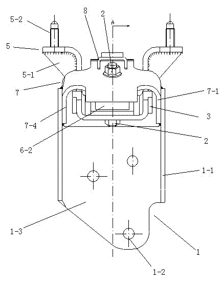
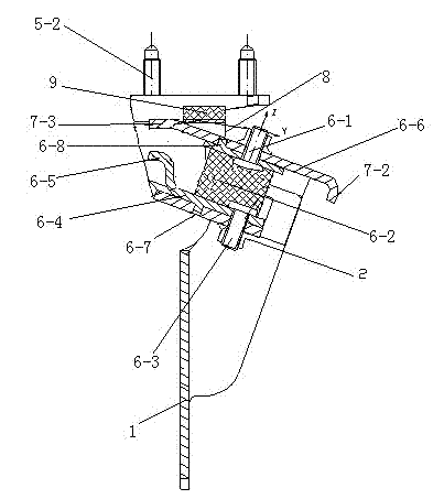
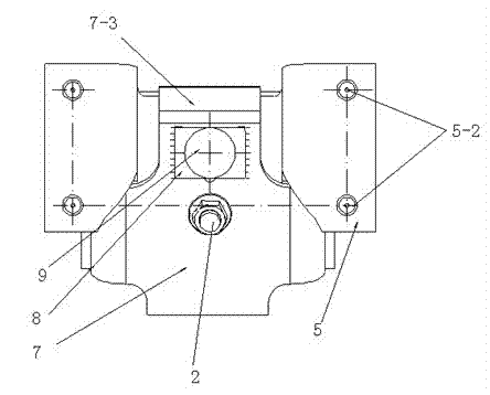
[0030] Such as figure 1 , figure 2 , image 3 , Figure 4 , Figure 5 , Figure 6 and Figure 7 The shown engine suspension cushion comprises an upper frame 5, a lower frame 7, a shock-absorbing member 6 connected between the upper frame 5 and the lower frame 7, a small bracket 8 connected to the top of the lower frame 7, and a small bracket connected to the lower frame 7. The large bracket 1 on both sides of the lower part, the upper frame 5 is in the shape of a groove, the two sides of the mouth of the groove are respectively the first flange 5-3, and the two first flanges 5-3 are respectively provided with two vertically connected flanges. There is a first stud 5-2, and there is a forward extension 5-4 at the bottom of the groove, and a stud hole and a positioning pin hole are provided on the extension 5-4; the lower frame 7 is an inverted "U" ” shape, the le...


PUM


Abstract

The invention relates to an engine suspension cushion which comprises an upper framework, a lower framework, a damping component connected between the upper framework and the lower framework, a small bracket connected with the upper surface of the top part of the lower framework and a big bracket connected with the two sides of the lower part of the lower framework, wherein the upper framework is groove-shaped; the two sides of the opening part of the groove are respectively first turn-up sides; the two first turn-up sides are respectively provided with a first stud which is vertically connected to each first turn-up side; a forward stretching section is arranged at the bottom of the groove; a stud hole and a positioning pin hole are formed in the stretching section; the lower framework is inversely U-shaped, the left side surface is a left faying surface while the right side surface is a right faying surface; the lower framework corresponds to the stretching section at the bottom of the groove of the upper framework; a stud hole and a positioning pin hole are formed in the top part of the lower framework; the damping component comprises an upper mounting plate, a lower mounting plate and a rubber cushion block arranged between the upper mounting plate and the lower mounting plate for connection. The engine suspension cushion disclosed by the invention is light in weight, high in rigidity and good in vibration isolation effect, and can meet the requirements on NVH (Noise Vibration and Harshness) and reliability.

Description

technical field [0001] The invention relates to automobile body components, in particular to an engine suspension cushion. Background technique [0002] In the process of arranging the rear suspension cushion of the engine, it is often encountered that the installation holes are arranged on the side of the transmission. In this case, the common method is to arrange an engine suspension cushion directly above the transmission, one end of the engine suspension cushion is connected with the transmission, and the other end of the engine suspension cushion is connected with the frame beam, so as to fix the power. assembly, but there are the following problems: 1. Since the engine suspension cushion is arranged directly above, there must be a certain motion envelope during the up and down movement of the vehicle. In order to avoid the collision of the engine mount cushion with the transmission and the frame beam, it is necessary to require the metal frame of the engine mount cush...

Claims


Application Information

Patent Timeline
Patent Type & Authority Applications(China)
IPC IPC(8): B60K5/12
Inventor 苏俊龙陈国良景建敏杨毅曾涛
Owner CHONGQING CHANGAN AUTOMOBILE CO LTD
Why Eureka
Try Eureka