Optical fiber pay-off device

A pay-off device and optical fiber technology, which is applied in the directions of transportation and packaging, delivery of filamentous materials, thin material processing, etc., can solve problems such as excessive attenuation, fiber breakage, and optical fiber damage, and achieve reduction of damage, elimination of sliding frictional resistance, The effect of reducing fiber breakage

Inactive Publication Date: 2014-02-19
TIANJIN YOFC XMKJ OPTICAL CABLE
View PDF5 Cites 8 Cited by
  • Summary
  • Abstract
  • Description
  • Claims
  • Application Information

AI Technical Summary

Problems solved by technology

After the existing pay-off rack releases the optical fiber from the pay-off reel, in order to ensure that the optical fiber passes through the middle of the guide wheel, a guide column is installed in front of the guide wheel, so that the optical fiber at both ends of the pay-off reel will enter the guide at a certain angle. Wheel, so that the guide column will produce considerable sliding friction on the optical fiber, which will eventually cause damage to the optical fiber, resulting in fiber breakage and excessive attenuation

Method used


Image

  • Optical fiber pay-off device

Examples


Embodiment Construction

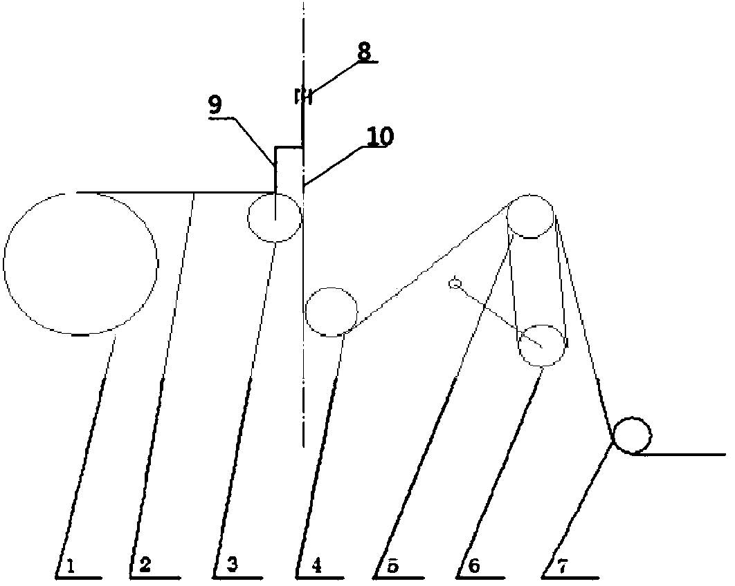
[0008] Specific embodiments of the invention will be described in detail below in conjunction with the accompanying drawings.

[0009] Such as figure 1 As shown in , the optical fiber 2 is released from the pay-off reel 1, and the optical fiber 2 is guided to the lower right positioning wheel 4 through the universal wheel 3, and then successively passes through the positioning wheel group 5 and the dancing wheel group 6 composed of two guide wheels , and finally enter the casing through the guide wheel 7. The universal wheel 3 is supported by a rotatable bracket 9 mounted on the top of the universal wheel 3. In order to allow the rotary bracket 9 to rotate freely, a bearing 8 is housed in the rotary bracket 9, so that the universal wheel 3 will follow the optical fiber 2 in unwrapping Disc 1 moves left and right and rotates to reduce friction; in order to further reduce friction, the center line 10 of the rotating shaft of the universal wheel support is tangent to the wheel g...


PUM


Abstract

The invention provides an optical fiber pay-off device which is used in the secondary coating procedure in optical fiber production. According to the technical scheme, an optical fiber is paid off from an optical fiber pay-off disc and guided by a universal wheel, a positioning wheel and a positioning wheel set, undergoes speed regulation conducted by a dancing wheel set and finally enters a sleeve. The universal wheel is supported by a rotatable support provided with a bearing. A universal wheel support rotating shaft center line is kept tangent to a wheel groove inner circle of the universal wheel and a wheel groove inner circle of the positioning wheel at the same time. Therefore, sliding friction force in the whole optical fiber walking route is greatly reduced, only small rolling friction force exists, and the quality of the optical fiber in the sleeve is ensured.

Description

technical field [0001] The invention relates to an optical fiber pay-off device, in particular to an optical fiber pay-off device in the secondary molding process in optical cable production. Background technique [0002] In the secondary molding process of optical cable production, in order to ensure the attenuation and excess length of the optical fiber are qualified, the optical fiber is required to be stable in tension on the pay-off rack without scratches. After the existing pay-off rack releases the optical fiber from the pay-off reel, in order to ensure that the optical fiber passes through the middle of the guide wheel, a guide column is installed in front of the guide wheel, so that the optical fiber at both ends of the pay-off reel will enter the guide at a certain angle. In this way, the guide column will produce considerable sliding friction on the optical fiber, which will eventually cause damage to the optical fiber, resulting in fiber breakage and excessive at...

Claims


Application Information

Patent Timeline
Patent Type & Authority Applications(China)
IPC IPC(8): B65H57/14B65H59/10
Inventor 毛志强孙志雄张增强赵岩孟祥浩阮灵刘莉
Owner TIANJIN YOFC XMKJ OPTICAL CABLE
Why Eureka
Try Eureka