Engine with low pumping loss and method for reducing engine pumping loss

A pumping loss and engine technology, which is applied in the field of engines with reduced pumping loss and low pumping loss, and can solve the problems of engine pumping loss, loss of engine energy, and low engine performance

Active Publication Date: 2016-03-02
GREAT WALL MOTOR CO LTD
View PDF4 Cites 0 Cited by
  • Summary
  • Abstract
  • Description
  • Claims
  • Application Information

AI Technical Summary

Problems solved by technology

Due to the small opening of the throttle valve and the small air intake of the engine under light load conditions, a large vacuum will be generated behind the throttle valve, causing the engine to have pumping loss; And in the exhaust stroke, because the piston is moving, there is a pressure difference between the top and bottom of the piston, so there is also a pumping loss in each of the above strokes. Experiments have shown that the pumping loss can lose about 15% of the energy of the engine. Resulting in lower performance of existing engines

Method used


Image

  • Engine with low pumping loss and method for reducing engine pumping loss
  • Engine with low pumping loss and method for reducing engine pumping loss
  • Engine with low pumping loss and method for reducing engine pumping loss

Examples


Embodiment Construction

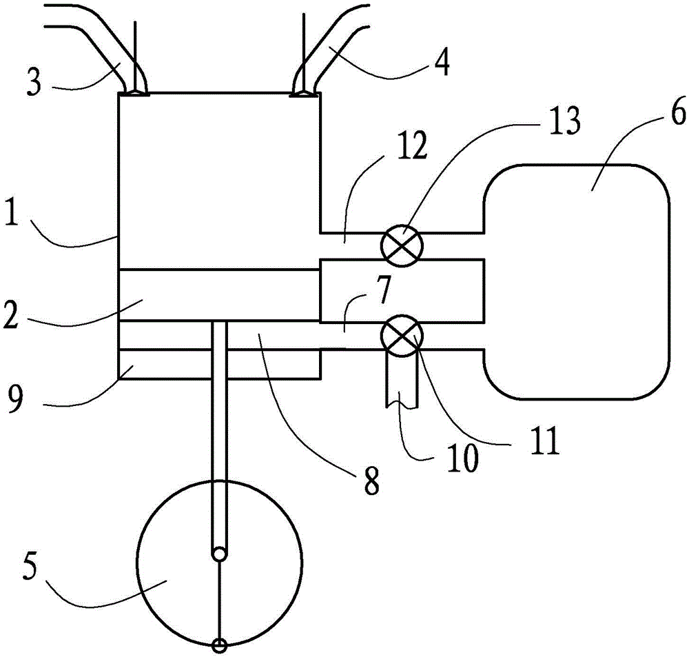
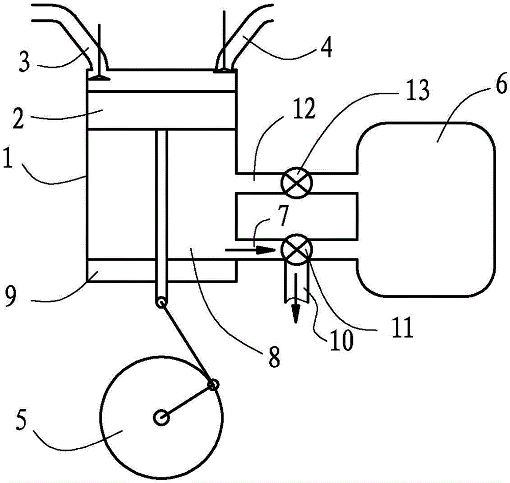
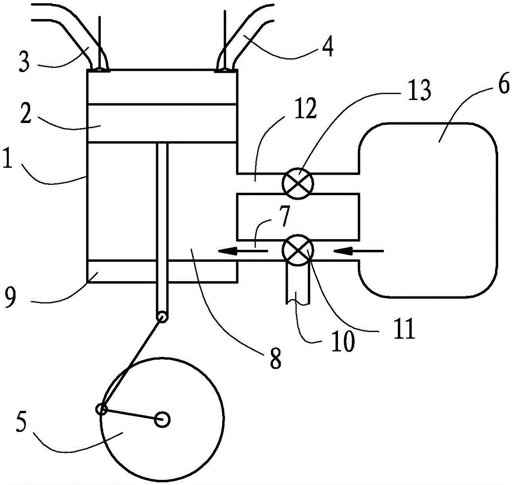
[0026] The engine of the low pumping loss that present embodiment relates to, by figure 1 As shown, it has a cylinder body 1, a piston 2 arranged in the cylinder body 1, an air inlet pipe 3 and an air outlet pipe 4 communicating with the inside of the cylinder body 1 are arranged on the top of the cylinder body 1, and the piston 2 is driven by the crankshaft mechanism 5. Next, move up and down in the cylinder block 1 to complete the intake, compression, work and exhaust strokes of the engine.

[0027] A gas storage device 6 is arranged outside the cylinder body 1, and the gas storage device 6 can adopt a device such as a gas storage tank to store gas in a sealed manner. A first pipeline 7 is connected between them, and the connection position between the first pipeline 7 and the cylinder body 1 is set at the lower section of the cylinder body 1, that is, close to the bottom dead center of the piston 2 in the cylinder body 1, so that when the piston 2 is located in the non- At...


PUM


Abstract

The invention relates to a low-pumping-loss engine which comprises a cylinder body, a piston arranged in the cylinder body, a gas storage device, a first pipeline and an exhaust pipe, wherein one end of the first pipeline is communicated with the part, close to a lower dead center of the piston, of the interior of the cylinder body, and the other end of the first pipeline is connected with the gas storage device; when the piston moves towards an upper dead center, gas in the gas storage device is conveyed into the cylinder body below the piston to push the piston upwards; the exhaust pipe is communicated with the interior of the cylinder body, and the piston moves downwards towards the lower dead center to enable gas, below the piston, inside the cylinder body to be discharged. The invention further relates to a method for reducing pumping loss of the engine. According to the technical scheme, when the piston moves upwards, gas is conveyed to the position below the piston through the gas storage device to enable the gas to be matched with a crack shaft to push the piston upwards, the difference between the pressure above the piston and the pressure below the piston is reduced when the piston moves upwards, and then pumping loss is reduced.

Description

technical field [0001] The invention relates to a structure of a reciprocating vehicle gasoline engine, in particular to an engine with low pumping loss; the invention also relates to a method for reducing the pumping loss of the engine. Background technique [0002] How to reduce the fuel consumption of the engine and improve the economy of the vehicle has been widely concerned by people. In the structure of the existing reciprocating vehicle gasoline engine, in order to reduce the fuel consumption of the engine, the existing method is to adjust the size of the intake air by changing the throttle, and then make the engine output different power and torque. Due to the small opening of the throttle valve and the small air intake of the engine under light load conditions, a large vacuum will be generated behind the throttle valve, causing the engine to have pumping loss; And in the exhaust stroke, because the piston is moving, there is a pressure difference between the top an...

Claims


Application Information

Patent Timeline
Patent Type & Authority Patents(China)
IPC IPC(8): F02B75/40
Inventor 崔亚彬于文斌张宝东
Owner GREAT WALL MOTOR CO LTD
Why Eureka
Try Eureka