
Power split planetary ring bevel gear type continuously variable transmission

A continuously variable transmission, planetary ring cone technology, applied in the direction of gear transmission, belt/chain/gear, transmission parts, etc., can solve the problems of unstable operation, large slip rate, low bearing capacity, etc., to avoid power backflow , good startability and long service life

Inactive Publication Date: 2015-11-25
ZHONGBEI UNIV
View PDF5 Cites 1 Cited by
  • Summary
  • Abstract
  • Description
  • Claims
  • Application Information

AI Technical Summary

Problems solved by technology

The CVT of hydraulic transmission requires high manufacturing precision and is expensive. Because the output characteristic is constant torque and the slip rate is large, oil leakage is prone to occur during operation; the CVT of electric transmission can be divided into electromagnetic sliding CVT Transmission, DC motor type continuously variable transmission and AC motor type continuously variable transmission, they have large slip rate, low efficiency, not suitable for long-term debt operation, complex equipment, high cost, mechanical characteristics showing constant torque in the deceleration section, poor operation Stability and other disadvantages; while the mechanically driven continuously variable transmission has simple structure, convenient maintenance, relatively cheap price, stable speed, small slip rate, and reliable operation. Since the mechanically driven continuously variable transmission mainly relies on friction to improve power, the carrying capacity is low. , generally suitable for medium and small power transmission

Method used


Image

  • Power split planetary ring bevel gear type continuously variable transmission
  • Power split planetary ring bevel gear type continuously variable transmission
  • Power split planetary ring bevel gear type continuously variable transmission

Examples


Embodiment Construction

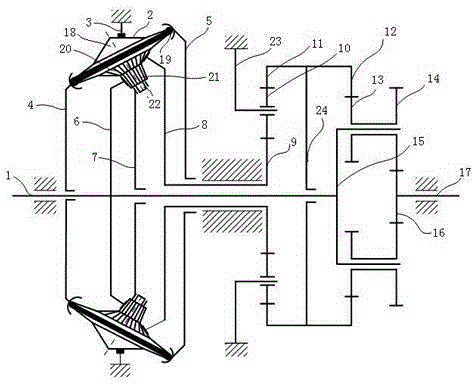
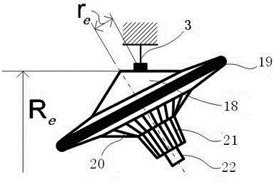
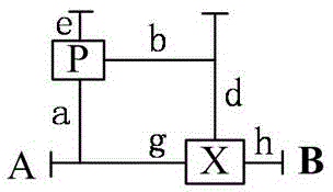
[0016] Power split ring bevel gear type continuously variable transmission, the transmission principle is the combination of planetary ring bevel gear type continuously variable transmission and differential gear train, the transmission structure is as follows figure 1 As shown, it includes power input shaft 1, planetary ring bevel gear 2, speed regulating ring 3, small support ring 4, large support ring 5, driving central bevel gear 6, planetary bevel gear cage 7, driven central bevel gear 8 , synchronous cylindrical gear 9, fixed axis gear 10, central internal meshing gear 11, synchronous internal meshing gear 12, planetary gear 13, synchronous planetary gear 14, planet carrier 15, output sun wheel 16, output shaft 17; small support ring 4, Planetary ring bevel gear cage 7 and driven central bevel gear 8 are vacantly sleeved on power input shaft 1, large support ring 5 is vacantly sleeved on driven central bevel gear 8, and active central bevel gear 6 and planet carrier 15 ar...


PUM


Abstract

The invention provides a power splitting planetary ring bevel gear type stepless speed changer. A planetary ring bevel gear type stepless speed changer and a differential gear train are combined. A small part of power is transmitted through rotation and revolution of planetary ring bevel gears and the differential gear train, most of power is transmitted through a power input shaft and a planetary carrier, and the two parts of power are synthesized on synchronous planetary gears and then transmitted to an output shaft, so that power splitting is finished. Stepless speed changing drive is achieved through changing the contact radius of the speed regulation rings and the planetary ring bevel gears. The power splitting planetary ring bevel gear type stepless speed changer has the advantages of being stable in drive, good in starting performance, capable of being stably started from zero under full loads and adapted to work of variable working conditions, long in service life and wide in speed changing range. In comparison with an existing planetary type stepless speed changer, the power splitting can be achieved, meanwhile, power reflowing is avoided, high power transmission is achieved, geometrical slipping is reduced to the minimum, and transmission efficiency is higher.

Description

technical field [0001] The invention relates to a mechanically driven continuously variable transmission, in particular to a power split planetary ring bevel gear type continuously variable transmission. Background technique [0002] At present, the transmission mode of continuously variable transmission is divided into three categories, namely hydraulic transmission, electric transmission and mechanical transmission. The CVT of hydraulic transmission requires high manufacturing precision and is expensive. Because the output characteristic is constant torque and the slip rate is large, oil leakage is prone to occur during operation; the CVT of electric transmission can be divided into electromagnetic sliding CVT Transmission, DC motor type continuously variable transmission and AC motor type continuously variable transmission, they have large slip rate, low efficiency, not suitable for long-term debt operation, complex equipment, high cost, mechanical characteristics showing...

Claims


Application Information

Patent Timeline
Patent Type & Authority Patents(China)
IPC IPC(8): F16H3/76F16H57/023F16H57/08
CPCF16H3/76F16H57/023F16H57/08
Inventor 毛虎平王军董小瑞杨世文张翼李建军张艳岗冯耀南尤国栋徐俊峰
Owner ZHONGBEI UNIV
Learn More