Fixture and method for measuring maximum tensile and shearing force of lap joint of friction stir welding

A technology of friction stir welding and lap joints, which is applied to measuring devices, using stable shear force to test material strength, and using stable tension/pressure to test material strength, etc., can solve the influence of measurement results and the inability to load On the same straight line, etc., to achieve the effect of eliminating the additional bending moment

Active Publication Date: 2014-02-19
HARBIN INST OF TECH
View PDF4 Cites 14 Cited by
  • Summary
  • Abstract
  • Description
  • Claims
  • Application Information

AI Technical Summary

Problems solved by technology

[0003] The purpose of the present invention is to solve the problem that in the traditional tensile shear test, the loads loaded on both sides of the tensile shear measurement specimen cannot be on the same straight line, and the additional bending moment has a negative impact on the measurement results of the maximum tensile shear force of the friction stir welded lap joint. A fixture and measurement method for measuring the maximum tensile and shear force of friction stir welded lap joints are proposed

Method used


Image

  • Fixture and method for measuring maximum tensile and shearing force of lap joint of friction stir welding
  • Fixture and method for measuring maximum tensile and shearing force of lap joint of friction stir welding
  • Fixture and method for measuring maximum tensile and shearing force of lap joint of friction stir welding

Examples


specific Embodiment approach 1

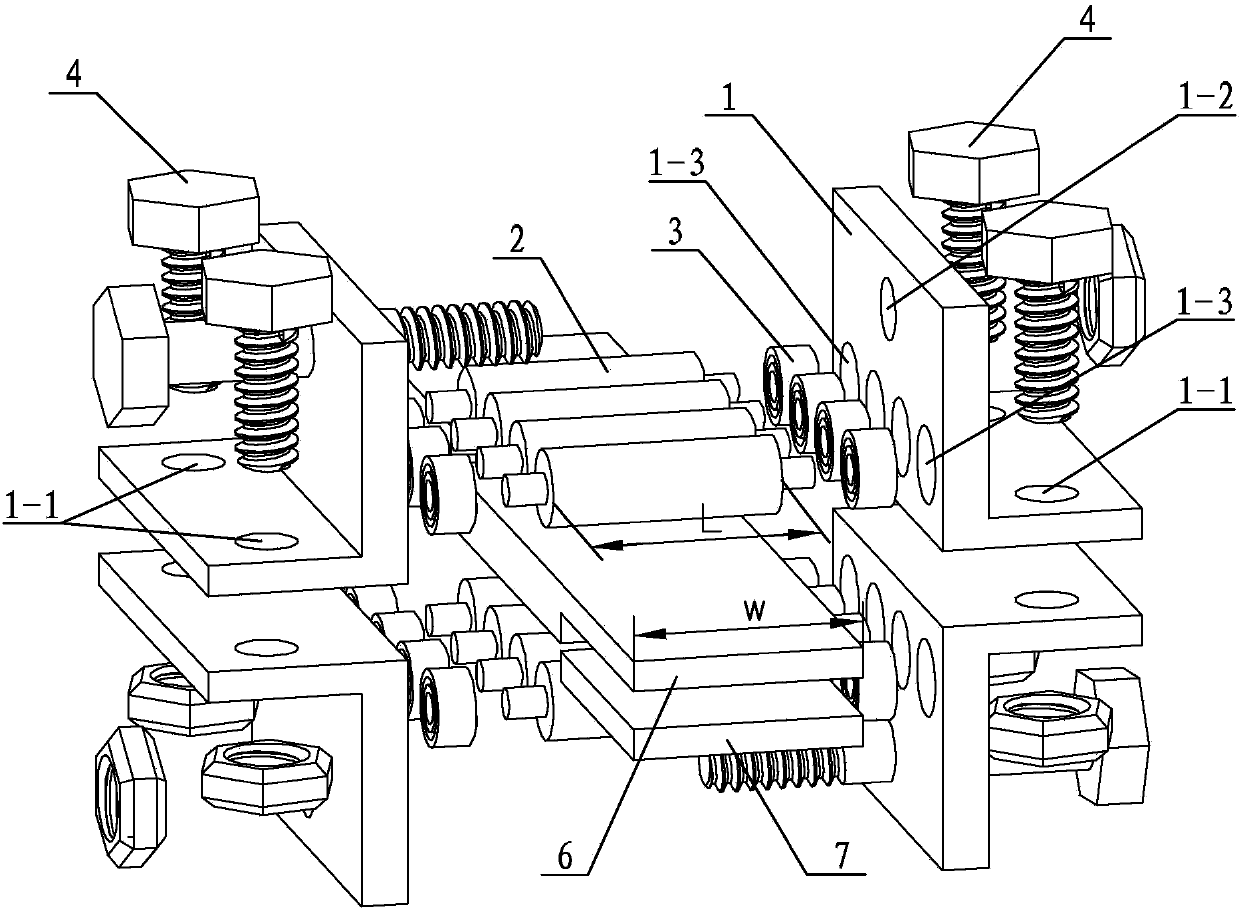
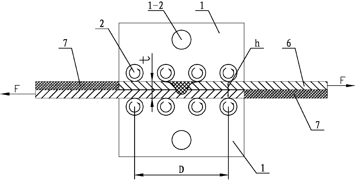
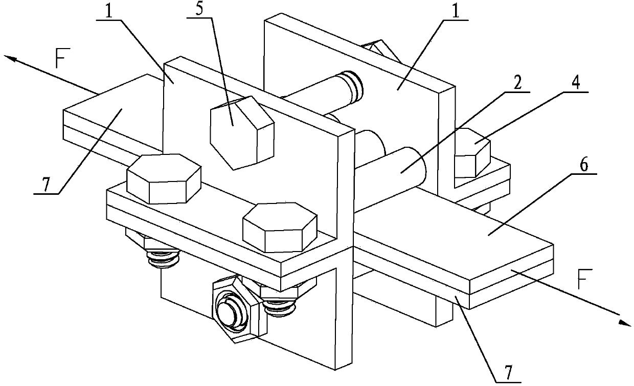
[0015] Specific implementation mode one: combine Figure 1 ~ Figure 3 Describe this embodiment, this embodiment includes two second connecting elements 5, four L-shaped support plates 1, four first connecting elements 4, eight rollers 2 and sixteen positioning bearings 3, each L Two first connection holes 1-1 are provided on the short plate of the L-shaped support plate 1, and a second connection hole 1-2 and four bearing mounting holes 1-3 are provided on the long plate of each L-shaped support plate 1 , the four bearing mounting holes 1-3 are arranged along the same horizontal line, and the long plate of each L-shaped support plate 1 is provided with four bearing mounting holes 1-3 at the bottom, and the eight rollers 2 are arranged in two layers, each layer Four rollers 2 are arranged in parallel, the four rollers 2 on the upper layer are arranged opposite to the four rollers 2 on the lower layer one by one, two L-shaped support plates 1 are symmetrically arranged at both e...

specific Embodiment approach 2

[0016] Specific implementation mode two: combination figure 1 Describe this embodiment, the roller shaft 2 of this embodiment is a stepped shaft, the diameter of both ends is smaller than the diameter of the middle working part. Other components and connections are the same as those in the first embodiment.

specific Embodiment approach 3

[0017] Specific implementation mode three: combination figure 1 This embodiment will be described. In this embodiment, the roller 2 and the positioning bearing 3 are interference fit. Other compositions and connections are the same as those in Embodiment 1 or 2.


PUM


Abstract

The invention provides a fixture and a method for measuring the maximum tensile and shearing force of a lap joint of friction stir welding to overcome the problem that additional bending moment influences measurement results of the maximum tensile and shearing force of a lap joint of friction stir welding in a traditional tensile and shearing test. According to the fixture, four bearing installing holes are arranged along a same horizontal line; eight rollers are arranged in two layers, each layer consisting of four parallely arranged rollers; the end parts of each roller is mounted in a corresponding bearing installing hole through a positioning bearing. The method comprises the following steps: 1, allowing the distance between axle centers of two rollers located at two outermost sides of each layer of rollers to be 10 to 20 times thickness of the lap part of a test piece for tensile and shearing testing; 2, placing the test piece for tensile and shearing testing between the upper layer of rollers and the lower layer of rollers; and 3, clamping the assembled test piece for tensile and shearing testing, the fixture and cushion blocks on a tensile and shearing testing machine, carrying out tensile and shearing testing on the test piece for tensile and shearing testing at a loading speed of 0.5 to 1.5 mm / min and recording a maximum tensile and shearing test load F. The fixture and the method provided by the invention are used for measuring the maximum tensile and shearing force of the lap joint of friction stir welding.

Description

technical field [0001] The invention relates to a fixture and a measuring method for measuring the tensile shear force of a friction stir welding lap joint, in particular to a fixture and a measuring method for measuring the maximum tensile shear force of a friction stir welding lap joint. Background technique [0002] Friction stir lap welding is a relatively new solid-phase joining technology. Compared with traditional riveting technology, it can significantly reduce structural weight and improve joint quality. In addition, it has the advantages of low production cost and no environmental pollution. The most important performance index for evaluating friction stir lap joints is the maximum tensile shear force; in the process of tensile shear test of traditional friction stir welded lap joints, due to the asymmetry of lap joints, it is impossible to make the load in tension The load on both sides of the shear measurement specimen is on the same straight line, thereby genera...

Claims


Application Information

Patent Timeline
Patent Type & Authority Applications(China)
IPC IPC(8): G01N3/04G01N3/08G01N3/24
Inventor 刘会杰赵运强陈诗璇林喆
Owner HARBIN INST OF TECH
Why Eureka
Try Eureka