
A detection method for dynamic load distribution of vehicles on long-span bridges

A dynamic load and distribution detection technology, applied in image analysis, image data processing, instruments, etc., can solve the problems of complex structural forms, poor real-time performance, and sensor influence of long-span bridges

Active Publication Date: 2016-09-28
CHANGAN UNIV
View PDF3 Cites 0 Cited by
  • Summary
  • Abstract
  • Description
  • Claims
  • Application Information

AI Technical Summary

Problems solved by technology

Because the long-span bridge has the characteristics of complex structure, large span, and harsh environment, it brings many disadvantages to the dynamic load distribution detection of bridge vehicles, such as the number of sensors required is large, the cost is high, and the interference signal is easy to cause damage to the sensors. Influence, wiring is easy to be confused, the workload of arranging and maintaining equipment is relatively large, and the real-time performance is poor, etc.

Method used


Image

  • A detection method for dynamic load distribution of vehicles on long-span bridges
  • A detection method for dynamic load distribution of vehicles on long-span bridges
  • A detection method for dynamic load distribution of vehicles on long-span bridges

Examples


Embodiment 1

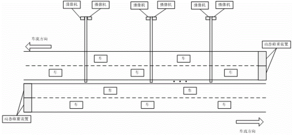
[0094] Step 1. Install a dynamic weighing device at the entrance of each lane of the long-span bridge to obtain vehicle weight information, and install a camera on the bridge to obtain bridge deck images. The camera's field of view can cover the entire bridge deck.

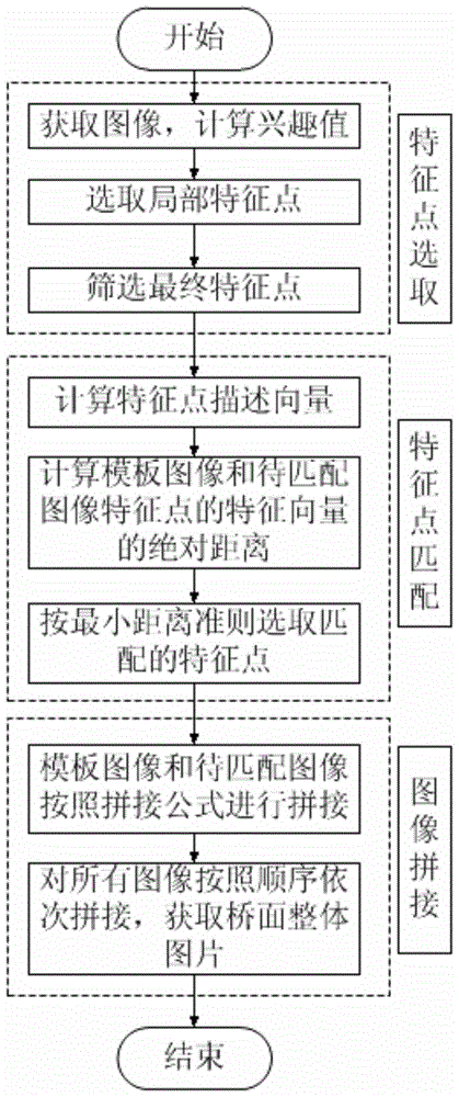
[0095] Step 2, splicing the bridge deck images acquired by the camera to obtain a panoramic image of the entire bridge deck:

[0096] (2.1) For the images taken by two adjacent cameras on the long-span viaduct, the images taken by the two cameras at the same time are respectively taken, such as Figure 7 and Figure 8 as shown, Figure 7 for the template image, Figure 8 is the image to be matched; Figure 7 Using the Harris operator to extract feature points, the result is as follows Figure 9 shown, yes Figure 8 Using the Harris operator to extract feature points, the result is as follows Figure 10 shown.

[0097] select Figure 9 The 10 feature points closest to the right boundary area and Figure 10...

Embodiment 2

[0152]The next frame image in this embodiment is the next frame image of the current frame image in embodiment 1, and the first two frame images of the next frame in this embodiment are the previous frame image of the current frame in embodiment 1, The previous frame image of the next frame in this embodiment is the current frame image in Embodiment 1.

[0153] Step 1 and Step 2 in the method of this embodiment are the same as Step 1 and Step 2 in the method of Embodiment 1.

[0154] Step 3: After obtaining the panoramic image of the entire bridge deck, three consecutive frames of images at the previous moment are taken in the process of detecting moving objects by using the method of hybrid difference and edge detection, as shown in Figure 14 , Figure 15 and Figure 20 as shown, Figure 14 For the first two frames of the next frame, Figure 15 is the previous frame image of the next frame, Figure 20 for the next image frame. Using the same method as Step 3 of Embodim...


PUM


Abstract

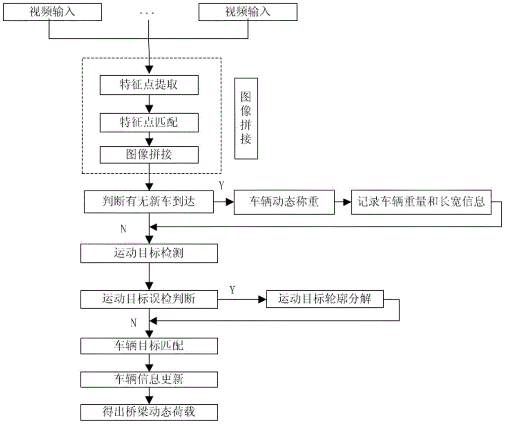
The present invention proposes a method for detecting dynamic load distribution of long-span bridge vehicles. The method utilizes a dynamic weighing device, adopts image splicing and multi-vehicle detection, and realizes real-time collection, real-time processing and real-time analysis of long-span bridge load data, and provides bridge Management and maintenance provide the basis. Wherein, in the mosaic process, the image mosaic algorithm based on the Harris operator is used to remove the overlapped part of the image. After obtaining the real-time panoramic image of the bridge deck, the multi-vehicle detection algorithm is used to track the vehicle and obtain the vehicle position. Finally, according to the vehicle weight obtained by the dynamic weighing device and the vehicle position obtained by the multi-vehicle detection algorithm, combined with the bridge design parameters, the real-time load of the bridge is calculated.

Description

technical field [0001] The invention belongs to the field of bridge detection, and relates to a detection method of a long-span bridge load, in particular to a detection method of a dynamic load distribution of a large-span bridge vehicle. Background technique [0002] The dynamic load distribution of bridge vehicles plays a very important role in the process of bridge design and operation, and is an important parameter in the process of bridge real-time monitoring. In recent years, some bridges have been crushed by overloaded and overweight vehicles from time to time. A large number of illegal overloaded and overweight vehicles have entered the bridge, causing serious damage to the bridge structure and bringing serious hidden dangers to the safe operation of the bridge. Once a danger occurs, it will cause irreparable damage. Loss. Therefore, it is necessary to monitor the bridge in real time. During the monitoring process, it is particularly important to detect the dynamic...

Claims


Application Information

Patent Timeline
Patent Type & Authority Patents(China)
IPC IPC(8): G06K9/64G06T5/50G06T3/40G06T7/00
Inventor 赵祥模徐志刚张立成任亮梁超程鑫白国柱周经美
Owner CHANGAN UNIV
Learn More