Electricity transmission device for wireless power communication system
A communication system and wireless power technology, applied in battery circuit devices, circuit devices, electromagnetic wave systems, etc., can solve problems such as unsightly contact ports, poor contact, pollution, etc., and achieve the effect of improving receiving sensitivity and shielding degree
- Summary
- Abstract
- Description
- Claims
- Application Information
AI Technical Summary
Problems solved by technology
Method used
Image

Examples
Embodiment Construction
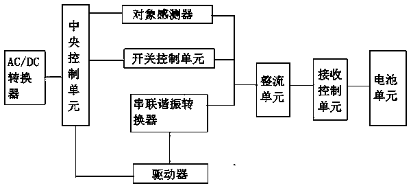
[0009] In this example, refer to figure 1 As shown, a power transmission device for a wireless power communication system includes an AC / DC converter, a central control unit, an object sensor, a switch control unit, a series resonant converter, a driver, a rectifier unit, a receiving control unit, and a battery unit , the AC / DC converter is connected to the central control unit, the central control unit is connected to the object sensor, the switch control unit is connected to the central control unit, the central control unit is connected to the driver, and the driver is connected to the A series resonant converter is connected, the series resonant converter is connected to the object sensor, and the object sensor, the switch control unit and the series resonant converter are respectively connected to the rectifying unit.
[0010] The rectifying unit is connected with the receiving control unit, and the receiving control unit is connected with the battery unit.
[0011] An e...
PUM
 Abstract
Description
Claims
Application Information
 - R&D
- Intellectual Property
- Life Sciences
- Materials
- Tech Scout
- Unparalleled Data Quality
- Higher Quality Content
- 60% Fewer Hallucinations
Browse by: Latest US Patents, China's latest patents, Technical Efficacy Thesaurus, Application Domain, Technology Topic, Popular Technical Reports.
© 2025 PatSnap. All rights reserved.Legal|Privacy policy|Modern Slavery Act Transparency Statement|Sitemap|About US| Contact US: help@patsnap.com