
Method of making a monolithic magnetic read-while-write head apparatus

Inactive Publication Date: 2007-09-11
IBM CORP
View PDF21 Cites 13 Cited by
  • Summary
  • Abstract
  • Description
  • Claims
  • Application Information

AI Technical Summary

Benefits of technology

[0017]It is a purpose of this invention to reduce the cost of separately fabricating, finishing and assembling each recording head by aligning many recording heads at once on both sides of a single wafer and eliminating the requirement for separate finishing of multiple modules for a single recording head. It is a feature of this invention that monolithic MR tape heads are fabricated on both surfaces of a single wafer.
[0018]It is another purpose of this invention to eliminate the usual requirement for a conductive shield between track-pair elements of a MR magnetic tape head. It is an advantage of the tape head of this invention that such cumbersome shield is unnecessary because the conductive substrate material provides all necessary shielding. However, it is also an advantage of the method of this invention that a thin film conductive layer such as, for instance, gold or copper, may be formed under the elements on either or both sides of the wafer for improved shielding.

Problems solved by technology

Also, the two thin-film modules 22 and 24 (FIG. 1) must be aligned along the track line of motion of the tape medium and joined together within a small fraction of the data track width, which is a slow and expensive process with high spoilage rates during manufacture.
The disadvantages of the interleaved MR head discussed above apply also to the “piggy-back” head known in the art.
The present state of the art requires independent finishing of the air bearing surfaces for two or three modules to submicron precision and the independent precise assembly of these modules into a recording head, with much cost and difficulty.

Method used


Image

  • Method of making a monolithic magnetic read-while-write head apparatus
  • Method of making a monolithic magnetic read-while-write head apparatus
  • Method of making a monolithic magnetic read-while-write head apparatus

Examples


Embodiment Construction

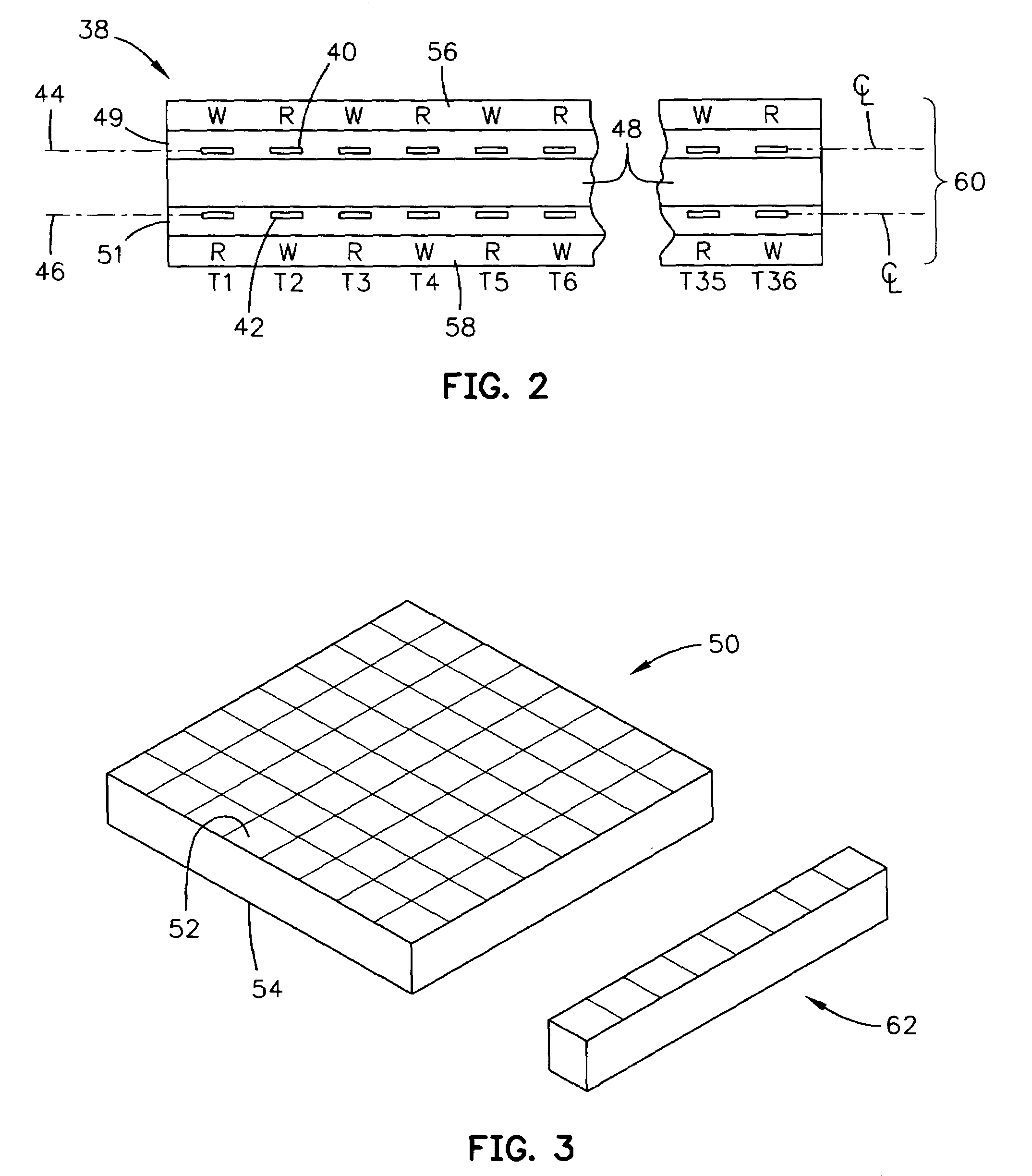
[0031]FIG. 2 illustrates a front view of the air bearing surface (ABS) of a magnetoresistive (MR) head assembly 38 according to the present invention. Head assembly 38 includes a plurality of read elements marked “R” and a plurality of write elements marked “W” exemplified by the read head 40 and the write head 42, which together form the R / W track-pair 40-42. Read head 40 is disposed at the head gap line 44 and write head 42 is disposed at the head gap line 46. In accordance with this invention, head gap lines 44 and 46 are disposed slightly below opposite surfaces of a single monolithic substrate 48, which are covered by the overcoat layers 49 and 51. As used herein, the term monolithic denominates an undivided seamless piece. Monolithic substrate 48 is fabricated from a single substrate wafer 50 (FIG. 3) by using complete magnetic thin-film processing on both sides 52 and 54 of substrate wafer 50. Note that the head elements exemplified by read head 40 and write head 42 are align...


PUM

PropertyMeasurementUnit
Thicknessaaaaaaaaaa

Abstract

A method for fabricating a multi-track thin-film magnetoresistive tape head with precisely-aligned read / write track-pairs fabricated on a monolithic substrate wafer is provided. The wafer is fabricated using modified standard thin-film processes for fabricating direct access storage device heads and modified substrate lapping procedures. Gap-to-gap separation within each read / write track-pair is reduced to nearly the thickness of the substrate wafer. Fabricating on both sides of the wafer, may enable hundreds or thousands of head elements to be aligned in one step of the fabrication process while reducing the number of pieces in the completed head assembly.

Description

REFERENCE TO RELATED APPLICATION[0001]This is a divisional application of Ser. No. 09 / 877,382 filed Jun. 7, 2001, now U.S. Pat. No. 6,646,830.BACKGROUND OF THE INVENTION[0002]1. Field of the Invention[0003]This invention relates generally to read / write head arrays for magnetic data stores and more particularly to a monolithic magnetic read-while-write tape head.[0004]2. Description of the Prior Art[0005]Business, science and entertainment applications depend upon computers to process and record data, often with large volumes of the data being stored or transferred to nonvolatile storage media, such as magnetic discs, magnetic tape cartridges, optical disk cartridges, floppy diskettes, or floptical diskettes. Typically, magnetic tape is the most economical means of storing or archiving the data. Storage technology is continually pushed to increase storage capacity and storage reliability. Improvement in data storage densities in magnetic storage media, for example, has resulted from ...

Claims


Application Information

Patent Timeline
IPC IPC(8): G11B5/127H04R31/00G11B5/31G11B5/39G11B5/48
CPCG11B5/3103G11B5/3169G11B5/3173G11B5/3967G11B5/3116G11B5/4893Y10T29/49032Y10T29/49048Y10T29/49046Y10T29/49798Y10T29/49043Y10T29/49039Y10T29/49052
Inventor BISKEBORN, ROBERT GLENNEATON, JAMES HOWARD
Owner IBM CORP
Features
  • Generate Ideas
  • Intellectual Property
  • Life Sciences
  • Materials
  • Tech Scout
  • Unparalleled Data Quality
  • Higher Quality Content
  • 60% Fewer Hallucinations
Learn More