
Auxiliary valve controlled self-cleaning main valve

An auxiliary valve, self-cleaning technology, applied in the direction of valve operation/release device, valve detail, valve device, etc., can solve problems such as adding operation control piston

Inactive Publication Date: 2014-02-19
BERY INTPROP SZELLEMI TULAJDONJOGOKAT HASZNOSITO & KEZELO KORLATOLT FELELOSSEGU TARSASAG
View PDF7 Cites 0 Cited by
  • Summary
  • Abstract
  • Description
  • Claims
  • Application Information

AI Technical Summary

Problems solved by technology

By increasing the spring force, the temporary stuck situation caused by the aforementioned sticking situation can be eliminated, however, the force required to operate the valve stem that controls the piston must still be increased

Method used


Image

  • Auxiliary valve controlled self-cleaning main valve
  • Auxiliary valve controlled self-cleaning main valve
  • Auxiliary valve controlled self-cleaning main valve

Examples


Embodiment Construction

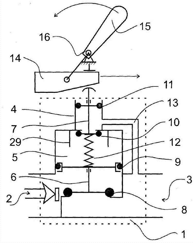
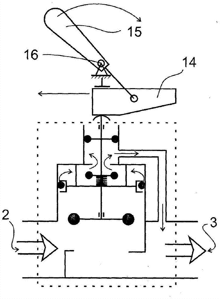
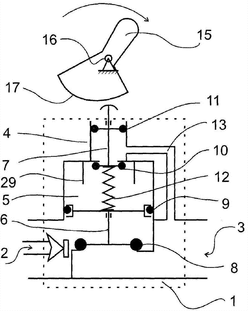
[0024] according to Figure 1a and Figure 1b In the first embodiment of the invention shown, the valve body 1 includes an inlet hole 2 and an outlet hole 3 interconnected with the flow-through holes. The portion enclosed by the dashed box illustrates the inventor's earlier patent, which is adapted for use with the present invention, as will be set forth in the following description.

[0025] The main flow passage of the valve body 1 can be closed or opened by the main closing element 8 depending on the position of the piston 6 . The main closing element is located on one (bottom) side of the piston 6 , while on its other (upper) side there is a brake O-ring 9 adjoining the control chamber 5 . As shown, the bumper 29 limits the upward movement of the piston 6 . These buffers can be separate elements or a single tube with a suitably sized orifice.

[0026] On one side of the control chamber 5 is provided an auxiliary valve 4 , which flows through holes so that the liquid flo...


PUM


Abstract

Auxiliary valve controlled self-cleaning main valve with mechanical operating means. The valve body (1) of the main valve has an inlet (2) and an outlet (3) interconnected through a flow-through opening, and a movable piston (6) having a main closing element (8) at one of its sides and a brake O-ring (9) at its other side. In the control chamber (5) an auxiliary valve (4) with a control valve stem (7) is provided. Between the piston (6) and the auxiliary valve (4) a compressible spring (12) is positioned. The mechanical operating means is provided with a wedge travel path and adapted to press the control valve stem (7) when force is applied externally and to keep it pressed in without applying external force, further it is adapted to release it when force is applied externally and to keep it released without applying external force.

Description

technical field [0001] The present invention relates to a self-cleaning main valve controlled by an auxiliary valve with a mechanical operating member, especially for large volume pipelines. In another approach, it is an indirectly controlled valve with an auxiliary valve equipped with a mechanism for keeping it open or closed for long periods of time. More precisely, the present invention is a main valve, the valve body of which is equipped with inlet and outlet holes interconnected with the flow-through holes, a movable piston, on one side of which there is a main closing element for when the piston is in its The flow-through hole is closed in one end position, and on the other side of the piston there is a brake O-ring adjoining the control chamber, which is in contact with the wall of the control chamber, thereby defining the first fluid flow A1. On the side of the control chamber opposite the flow-through orifice is provided an auxiliary valve with a control valve stem h...

Claims


Application Information

Patent Timeline
IPC IPC(8): F16K31/24F16K31/524
CPCF16K31/124F16K31/383F16K31/524
Inventor 约瑟夫·贝雷斯奈
Owner BERY INTPROP SZELLEMI TULAJDONJOGOKAT HASZNOSITO & KEZELO KORLATOLT FELELOSSEGU TARSASAG
Learn More