
Braking System

A brake system and brake fluid technology, applied in the direction of brake safety systems, brakes, ABS control systems, etc., can solve the problems of not being able to control the pressure accurately and effectively, not conforming to the brake circuit, etc.

Active Publication Date: 2018-07-24
ROBERT BOSCH GMBH
View PDF5 Cites 0 Cited by
  • Summary
  • Abstract
  • Description
  • Claims
  • Application Information

AI Technical Summary

Problems solved by technology

[0006] However, this formula does not correspond to the actual situation of the brake circuit, because the formula only characterizes the load loss of the hole type, and thus cannot control the pressure applied to the individual wheel brakes with sufficient accuracy and efficiency

Method used


Image

  • Braking System

Examples


Embodiment Construction

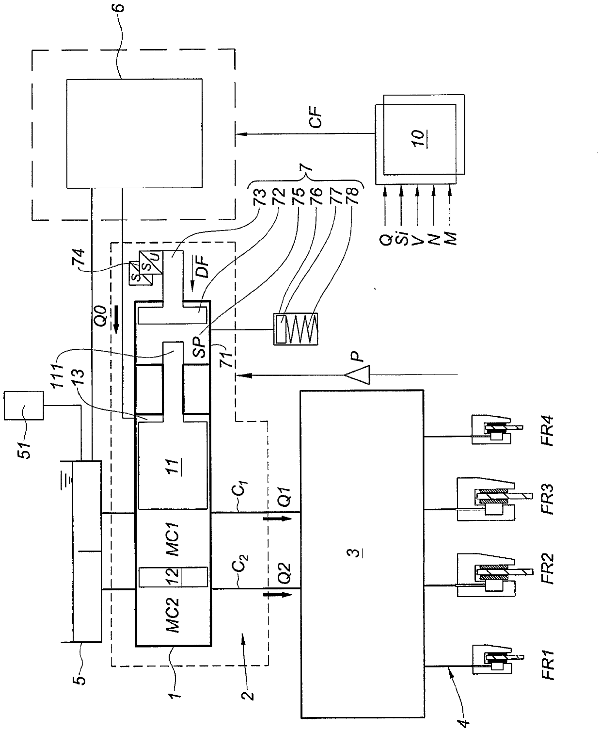
[0028] According to this figure, the object of the invention is a braking system comprising a master cylinder 1 (here a tandem master cylinder) connected to the brake circuit C1, C2 by a line 2, passing through Brake force regulator 3 is connected to wheel brake FR via line 4 1 -FR 4 , wherein the braking of the wheel brakes FR1-FR4 is controlled according to the driver's braking request DF, various signals SI provided by the sensors and the wheel reaction.

[0029] The master cylinder 1 comprises a primary piston 11 and a secondary piston 12, which respectively define a primary chamber MC1 and a secondary chamber MC2 connected to respective brake circuits C1, C2. The two chambers MC1 , MC2 are supplied with brake fluid from the reservoir 5 . The pressurized brake fluid supplied by the master cylinder 1 flows through the line 2 to the two circuits C1 , C2 comprising the brake force regulating device 3 upstream of the wheel brakes FR1 - FR4 . In this embodiment, the master c...


PUM


Abstract

The invention relates to a braking system comprising a master cylinder applying pressurized brake fluid to the wheel brakes via a device (3) for controlling the braking power of the different wheels. Said device (3) is managed by a control unit (10) which receives signals from different sensors monitoring the operation of the braking system and the driver's reactions and braking requests. Said braking system is characterized in that the braking power control unit (3) applies, to the wheel brakes (FR1-FR4), a pressure that is equal to the pressure (Pmc) at the outlet of the master cylinder (1) and reduced by a corrective term ΔΡ determined by the central control unit (10) and given by the following formula: ΔΡ = υM * Q + N * Q2, wherein υ is the viscosity of the brake fluid, Q is the flow rate provided by the master cylinder (1) to the wheel brakes (FR1- FR4), and M and N are constants specific to the physical characteristics of the brake circuits between the outlet of the master cylinder (1) and the wheel brakes (FR1-FR4).

Description

technical field [0001] The invention relates to a braking system comprising a master cylinder which applies pressurized brake fluid to the wheel brakes via a brake force modulating device for each wheel, which device is controlled by a control unit which receives the respective sensor The individual sensors monitor the operation of the brake system, the driver's reaction and the brake request. Background technique [0002] Currently, in auxiliary braking systems, such as brake assist systems ESP, ASR, etc., the regulating device controls the pressure of the brake fluid in the wheel brakes as a function of the driver's braking request and the signals provided by the sensors. [0003] The brake management system works downstream of the master cylinder and the servo brakes or their equivalent hydraulic or electrohydraulic brakes in order to regulate the pressure to the wheel brakes. However, it is currently only possible to determine in an imprecise manner the pressure losses ...

Claims


Application Information

Patent Timeline
Patent Type & Authority Patents(China)
IPC IPC(8): B60T8/172B60T17/22
CPCB60T8/172B60T17/226B60T2270/14
Inventor C.皮纳尔
Owner ROBERT BOSCH GMBH
Learn More