Transversely-wiping type windscreen wiper

A wiper and horizontal scraping technology, which is applied in the field of dirt devices, can solve the problems of the wiper blades being unable to move left and right, the phenomenon of rain followed by scraping, and dead angles that cannot be scraped, so as to avoid rain follow and scrape and prolong the aging time , The effect of smooth movement

Active Publication Date: 2014-02-26
SHENZHEN JIAHUI SCI & TECH IND CO LTD
View PDF7 Cites 5 Cited by
  • Summary
  • Abstract
  • Description
  • Claims
  • Application Information

AI Technical Summary

Problems solved by technology

Because most of the existing wipers wipe off rain, snow, dust, etc. by fanning the surface of the windshield, there are disadvantages such as limited range of wiping, leaving dead angles that cannot be scraped, and rain following the phenomenon of scraping. Therefore Chinese patent application CN102632868A discloses a kind of horizontal wiper vehicle wiper: "comprising wiper, transmission gear, it is characterized in that: also comprise upper slide rail, lower slide rail, upper slider, lower slider, transmission bead chain, guide pipe , fixing the base, the upper slide rail is installed near the upper edge of the windshield, and the upper slide rail is close to the windshield; the upper end of the wiper is flexibly connected with the upper slider, and the upper slider is installed on the upper slide rail, The lower end of the wiper is flexibly connected with the lower slider, and the lower slider is fixed on the transmission bead chain, and the transmission bead chain is installed in the circular track formed by connecting the lower rail and the guide pipe; the guide tube of the circular track, the gear and the transmission bead chain There is an opening at the transmission joint; the ring track is installed on a fixed base, the fixed base is installed on the lower edge of the windshield, the fixed base is provided with a dust cover, and the dust cover covers the ring track
"Though this windshield wiper that moves laterally on the surface of the windshield solves the above-mentioned shortcomings of the existing fan-shaped wiper, it also has the following disadvantages: the horizontal wiper is only connected to the lower end of the wiper blade. The power device, the movement of the upper end is driven by the movement of the lower end. In fact, due to the existence of frictional resistance between the upper slider and the upper slide rail, coupled with the non-linear track of the slide rail, this setting will cause the wiper blade to be hindered. As a result, it cannot move smoothly on the surface of the windshield

Method used


Image

  • Transversely-wiping type windscreen wiper
  • Transversely-wiping type windscreen wiper
  • Transversely-wiping type windscreen wiper

Examples


Embodiment 1

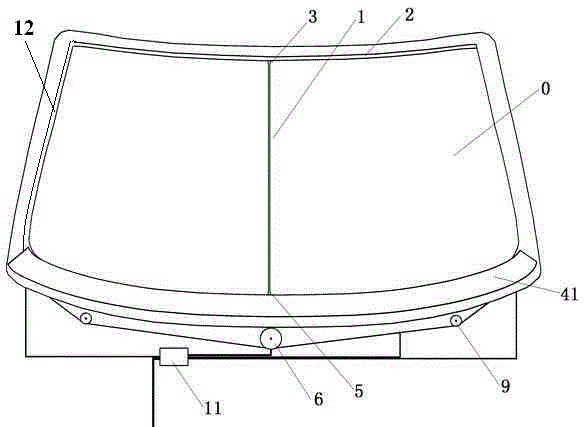
[0030] see figure 2 As shown, the horizontal wiper in this embodiment is mainly composed of a wiper blade 1, an upper slide rail 2, an upper slide block 3, a lower slide rail 4, a lower slide block 5, a motor 6, a guide elastic wheel 9 and a control switch 10 . The upper slide rail 2 is arranged on the upper edge of the windshield 0, and the upper slide rail 2 in this embodiment is a groove-shaped slide rail. The upper slider 3 is arranged on the upper slide rail 2, and can freely slide horizontally along the upper slide rail 2, such as Figure 4 , 5 As shown in . , the first roller 32 is located in the groove of the upper slide rail 2. The sliding rail 4 is arranged on the lower edge of the windshield 0, and the sliding rail 4 in the present embodiment is a groove-shaped sliding rail. The lower block 5 is arranged on the lower rail 4, and can slide freely along the lateral direction of the lower rail 4, such as Figure 4 As shown, the lower slider 5 in this embodiment ...

Embodiment 2

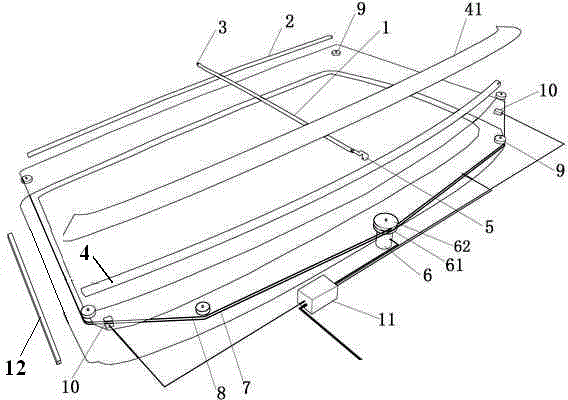
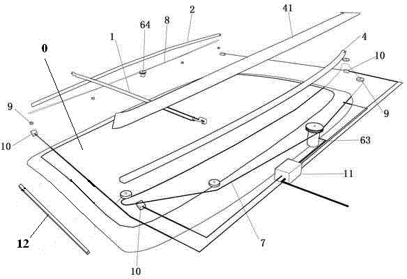
[0034] see image 3 As shown, the difference from Embodiment 1 is that in this embodiment, two motors are used to drive the reciprocating motion of the wiper blade 1, which are the first motor 63 fixedly connected to the lower slider 5 through the first transmission belt 7 and the first motor 63 through the The second transmission belt 8 is fixedly connected to the second motor 64 of the upper slider 3, and simultaneously, the upper slider 3 and the lower slider 5 are respectively provided with control switches for detecting their moving positions. When the upper slider 3 moves to the left end or the right end of the upper slide rail 2, the corresponding control switch for detecting its motion position controls the second motor 64 to rotate in reverse. When the lower slider 5 moves to the left end or the right end of the lower rail 4, the corresponding control switch that detects its motion position controls the first motor 63 to rotate in reverse.


PUM


Abstract

The invention provides a transversely-wiping type windscreen wiper and relates to a device for removing dirt such as rain, snow and dust obstructing the view of a user on a windscreen. According to the transversely-wiping type windscreen wiper, a dead corner of wiping and sweeping is avoided and the phenomenon that rainwater follows the wiper is effectively avoided. The transversely-wiping type windscreen wiper comprises a windscreen wiper blade vertically arranged on the surface of a windscreen and making contact with the windscreen, an upper sliding rail and a lower sliding rail. The upper end of the windscreen wiper blade is connected with an upper sliding block arranged on the upper sliding rail and the lower end of the windscreen wiper is connected with a lower sliding block arranged on the lower sliding rail. The transversely-wiping type windscreen wiper is characterized in that the upper sliding rail and the lower sliding rail are respectively a groove-shaped sliding rail, a barrier is arranged in each groove-shaped sliding rail in the length direction of the sliding rail, each groove-shaped sliding rail is divided into an inner groove and an outer groove through one barrier, the middle of each inner groove and the middle of the corresponding outer groove are communicated, at least two idler wheels are arranged in the grooves in the length direction of the sliding rails, and a wheel shaft of each idler wheel is parallel to the corresponding barrier.

Description

technical field [0001] The invention relates to a device for removing dirt such as rain, snow, dust and the like on the windshield, and particularly relates to a horizontal wiper wiper. Background technique [0002] Wiper, scientific name wiper (WINDSHIELD WIPER), refers to the sheet structure installed in front of the windshield, and its main function is to remove rain, snow, dust, etc. on the windshield that hinder the line of sight. Because most of the existing wipers wipe off rain, snow, dust, etc. by fanning the surface of the windshield, there are disadvantages such as limited range of wiping, leaving dead angles that cannot be scraped, and rain following the phenomenon of scraping. Therefore Chinese patent application CN102632868A discloses a kind of horizontal wiper vehicle wiper: "comprising wiper, transmission gear, it is characterized in that: also comprise upper slide rail, lower slide rail, upper slider, lower slider, transmission bead chain, guide pipe , fixin...

Claims


Application Information

Patent Timeline
Patent Type & Authority Applications(China)
IPC IPC(8): B60S1/44B60S1/38
CPCB60S1/20B60S1/3404B60S2001/3825B60S1/0814
Inventor 谭纲兴
Owner SHENZHEN JIAHUI SCI & TECH IND CO LTD
Why Eureka
Try Eureka