Tension roller adjustment device for traction machine of film stretching production line

A technology of adjusting device and production line, which is used in thin material handling, transportation and packaging, winding strips, etc., can solve the problem that the structure of the tension roller device is not reasonable enough, the tension roller cannot be adjusted to the film tension, and the load cell cannot accurately measure Film tension and other problems, to achieve the effect of accurate and reliable measurement value and simple device structure

Active Publication Date: 2016-01-06
GUILIN ELECTRICAL EQUIP SCI RES INST
View PDF9 Cites 0 Cited by
  • Summary
  • Abstract
  • Description
  • Claims
  • Application Information

AI Technical Summary

Problems solved by technology

[0002] In the tractor of the film stretching production line, the tension of the film passing between the rollers of the tractor is adjusted by the tension roller device, and the tension is measured by the load cell, but the existing tractor The structure of the tension roller device is not reasonable enough, which makes it difficult for the load cell to accurately reflect the tension of the film
[0003] The shaft end of the tension roller shaft of some existing tractor tension roller devices is connected to the motor through a coupling, so the tension of the tension roller to the film cannot be adjusted.
For other tractors, the motor transmits the speed and torque to the tension roller through the synchronous belt, and the tension force of the synchronous belt acts on the tension roller. The load cell cannot accurately measure the film passing between the rollers of the tractor. tension

Method used


Image

  • Tension roller adjustment device for traction machine of film stretching production line
  • Tension roller adjustment device for traction machine of film stretching production line
  • Tension roller adjustment device for traction machine of film stretching production line

Examples


Embodiment Construction

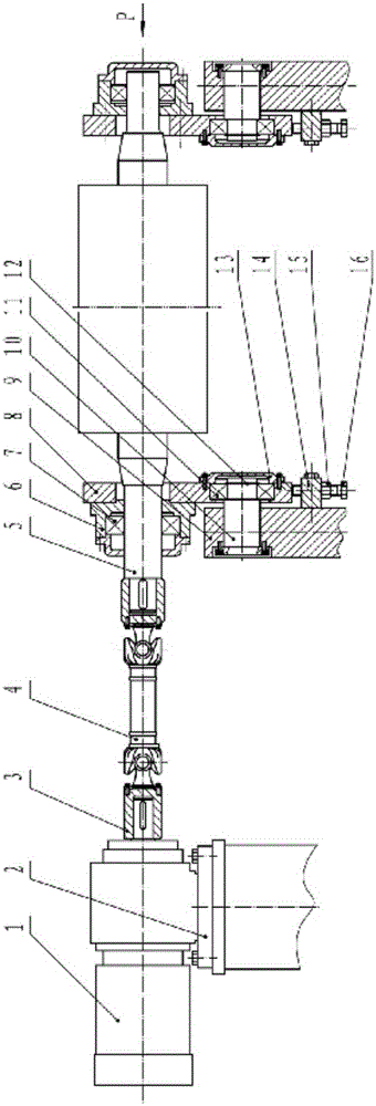
[0017] The overall structure schematic diagram of the embodiment of the tension roller adjustment device of the tractor in the film stretching production line is as follows figure 1 As shown, the motor 1 is fixed on the motor frame 2, and the two ends of the universal joint 4 are respectively connected to the output shaft of the motor 1 and the shaft end of the roller 5 shaft through the shaft sleeve 3 and the key and screw.

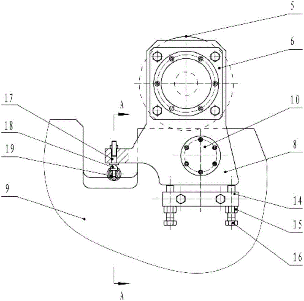
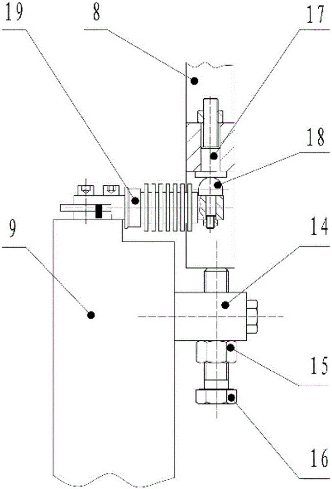
[0018] An identical swing arm 8 is respectively installed at the two ends of the roller 5, and the swing arm 8 has an upper hole and a lower hole. Bearing seat 6 is fixed on the outer side of the upper hole of swing arm 8 by bolt, and the outer ring of roller bearing 7 is fixed in the bearing seat 6, and the roller 5 shaft passes through the upper hole of swing arm 8 and is tightly inserted in the inner ring of roller bearing 7. The outer end of pin shaft 10 is fixedly installed on wallboard 9, and the center line of pin shaft 10 is parallel with roller ...


PUM


Abstract

The invention relates to a tension roll adjusting device for a film stretching line tractor. Two ends of a universal joint are connected with one end of an output shaft of a motor and one end of a roller shaft respectively. Two ends of a roller are provided with same swing arms respectively. The roller shaft is rotatably connected with upper holes of the swing arms. The other end of a pin with the outer end fixed to a wallboard is rotatably connected with a lower hole of each swing arm. A positioning plate fixed to each wallboard is disposed below each swing arm. Two adjusting bolts upwardly penetrate screw holes of the positioning plates, the upper ends of the adjusting bolts are abutted to the bottom ends of the swing arms, the adjusting bolts move up and down to drive the swing arms to swing, a roller of a tension roll is driven to swing, and tension of a film on the roller is adjusted. An arc-top top pin is fixed to one end of each weighing sensor fixed to the corresponding wallboard. A flat-bottom bottom pin is fixed to the bottom end of a side plate extending out of the rear of each swing arm. The bottom sides of the bottom pins are tangent with the tops of the top pins. The swing arms transmit tension to the weighing sensors though the bottom pins and the top pins so that the tension is measured. The tension roll adjusting device for the film stretching line tractor has the advantages that tension of the film is easy to adjust, measured tension values are accurate and reliable, and the device is simple in structure and easy to implement.

Description

technical field [0001] The invention relates to a mechanical structure of a tractor of a film stretching production line, in particular to a tension roller adjusting device of the tractor of a film stretching production line. Background technique [0002] In the tractor of the film stretching production line, the tension of the film passing between the rollers of the tractor is adjusted by the tension roller device, and the tension is measured by the load cell, but the existing tractor The structure of the tension roller device is not reasonable enough, which makes it difficult for the load cell to accurately reflect the tension of the film. [0003] The shaft end of the tension roller shaft of some existing traction machine tension roller devices is connected with the motor through a shaft coupling, so the tension roller can't adjust the tension of the film. For other tractors, the motor transmits the speed and torque to the tension roller through the synchronous belt, and...

Claims


Application Information

Patent Timeline
Patent Type & Authority Patents(China)
IPC IPC(8): B65H23/26
Inventor 马云华韦有共杨正昊龙成忠
Owner GUILIN ELECTRICAL EQUIP SCI RES INST
Why Eureka
Try Eureka