Method and system for locating and perceiving object in wireless sensor network

A wireless sensor and object positioning technology, which is applied in network topology, wireless communication, advanced technology, etc., can solve the problems of rising cost of wireless sensor nodes, achieve simple structure, reduce energy consumption, and reduce manufacturing costs

Active Publication Date: 2014-02-26
BEIJING UNIV OF POSTS & TELECOMM
View PDF2 Cites 13 Cited by
  • Summary
  • Abstract
  • Description
  • Claims
  • Application Information

AI Technical Summary

Benefits of technology

This technology uses special hardware devices with very limited capabilities for transmitting signals without being affected by external factors like noise or interference from other electronic components on nearby networks. It also allows each sensor element (a type called an inductor) to determine its own location accurately based solely upon their surrounding environment's electromagnetic waves. By doing this, fewer resources are needed than traditional methods while still maintain accurate data collection. Overall, these technical improvements improve efficiency and reduce power usage compared to current systems.

Problems solved by technology

The technical problem addressed in this patents relates to improving the efficiency and effectiveness of wirelessly sensed systems due to their ability to accurately locate targets without requiring expensive equipment like radometers. Current solutions involve either complex algorithms involving long periods of data acquisition or relying upon accurate timing measurements provided by conventional devices.

Method used


Image

  • Method and system for locating and perceiving object in wireless sensor network
  • Method and system for locating and perceiving object in wireless sensor network
  • Method and system for locating and perceiving object in wireless sensor network

Examples


Embodiment Construction

[0027] Specific embodiments of the present invention will be described in detail below in conjunction with the accompanying drawings. It should be understood that the specific embodiments described here are only used to illustrate and explain the present invention, and are not intended to limit the present invention.

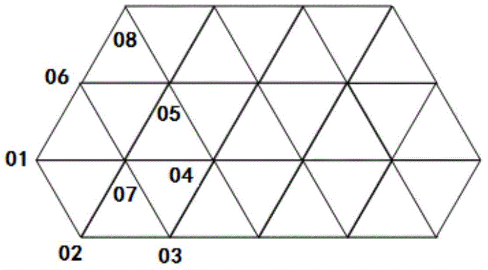
[0028] Through the research, it is found that when the object is on the communication path between the two nodes of WUSN, it will have a significant impact on the signal strength, the received signal strength will be significantly weakened or the signal cannot be received, and different objects have different influences on the signal strength. The decay is also different. The characteristics of the WUSN also exist in the wireless sensor network on the ground, so the technical solution provided by the present invention is not only applicable to the WUSN, but also can be applied to the wireless sensor network on the ground.

[0029]Wireless sensor networks have t...


PUM


Abstract

The invention discloses a method and a system for locating and perceiving an object in a wireless sensor network. The method comprises the following steps: a sensor node starts to send a detection message to a neighbor node after receiving a work instruction of a management node; the sensor node sends the identification of the sensor node and the identification of a first neighbor node to an aggregation node or a second neighbor node when judging that the signal strength of a detection message from the first neighbor node is lower than a threshold value, and then the identifications are sent to the management node by the aggregation node or are sent to the aggregation node by the second neighbor node and then are sent to the management node by the aggregation node; the sensor node sends the detection message to the neighbor node and receives the detection message from the neighbor node when judging that the signal strength of the detection message from the neighbor node is not lower than the threshold value. The method can shorten the working time of the nodes through network layout and logic judgment on the nodes, so that most of the nodes have long sleep time and energy consumption is reduced.

Description


Claims


Application Information

Patent Timeline
Owner BEIJING UNIV OF POSTS & TELECOMM
Why Eureka
Try Eureka