Bypass valve and supercharger

A bypass valve and valve body technology, which is applied in the direction of adding non-fuel substances to the machine/engine, fuel, exhaust gas recirculation, etc., can solve the problems that foreign matter is easy to mix into the bypass flow path, and foreign matter is easy to stay, so as to improve the operation efficiency , The effect of suppressing the reduction of pressure loss

Inactive Publication Date: 2014-02-26
IHI CORP
View PDF9 Cites 7 Cited by
  • Summary
  • Abstract
  • Description
  • Claims
  • Application Information

AI Technical Summary

Problems solved by technology

Therefore, in a supercharger with a bypass valve, since there is a recessed space in a part of the scroll portion (inside the bypass valve

Method used


Image

  • Bypass valve and supercharger
  • Bypass valve and supercharger
  • Bypass valve and supercharger

Examples


Embodiment Construction

[0033] Below, refer to Figure 1 ~ Figure 6B Embodiments of the present invention will be described.

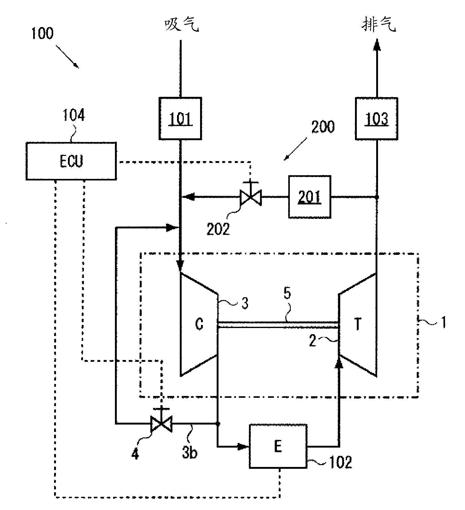
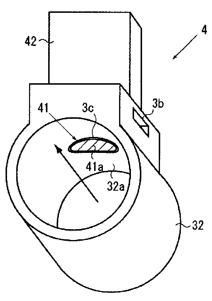
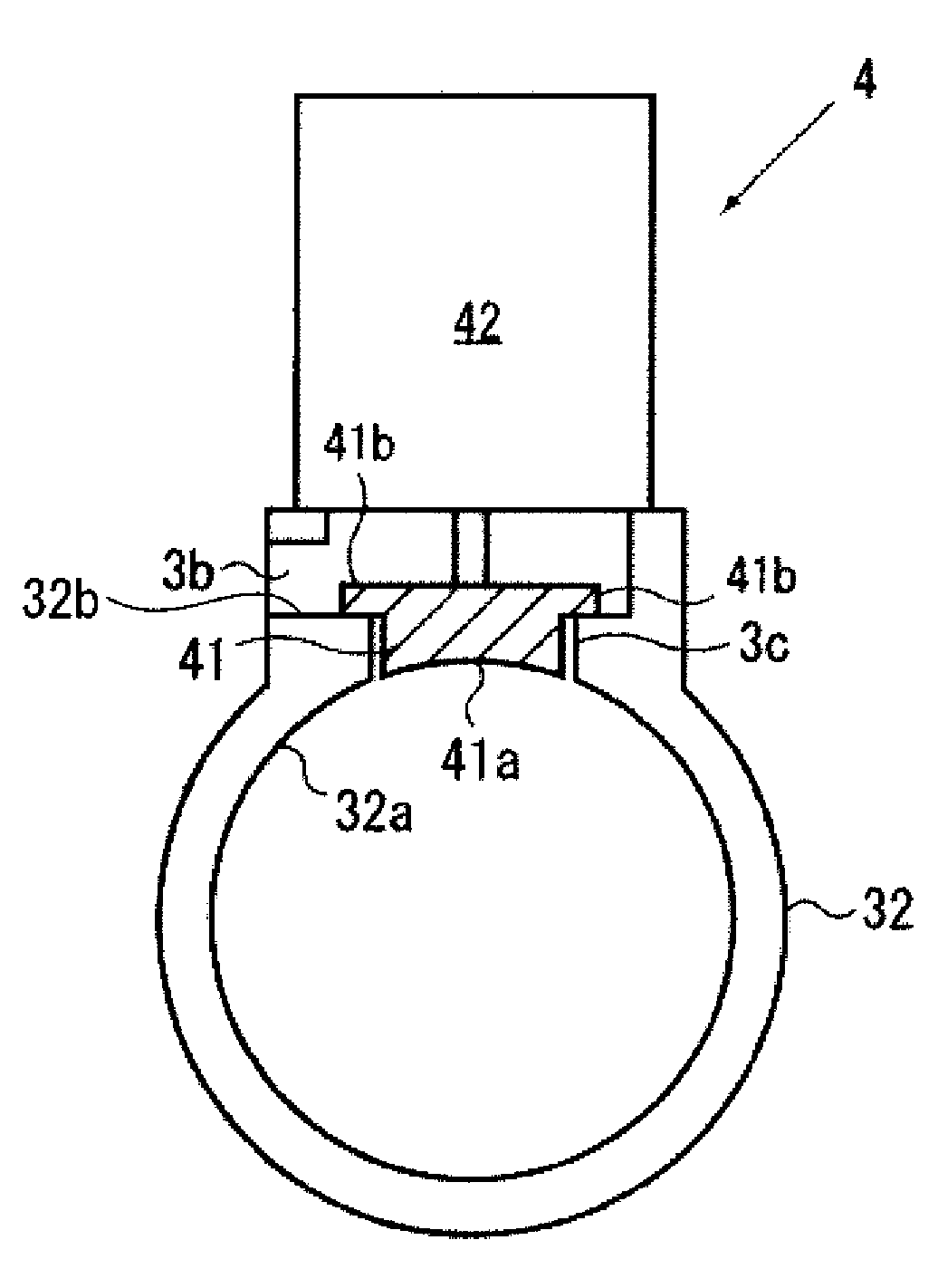
[0034] Such as figure 1 and figure 2 As shown, the supercharger 1 according to the first embodiment of the present invention includes: a gas turbine 2 to which exhaust gas is supplied from an engine 102 to rotate the movable blades 21; and a compressor 3 coaxially connected to the movable blades 21 The impeller 31 sucks in air, and the compressor casing 3 a constituting the casing of the compressor 3 has a scroll portion 32 formed in a spiral shape around the rotation axis of the impeller 31 . In addition, a bypass valve 4 is formed on the compressor housing 3a, and when the bypass valve 4 is opened, a part of the compressed air in the scroll portion 32 flows to the upstream side of the scroll portion 32 through the bypass flow path 3b. The flow is divided, and the compressed air in the scroll portion 32 is sent to the downstream side in the closed state. The bypass val...


PUM


Abstract

A bypass valve which, in an open state, diverts a part of compressed air within a scroll section to the upstream side of the scroll section through a bypass conduit, and which, in a closed state, allows the compressed air within the scroll section to flow to the downstream side. The bypass valve is provided with: a valve body which is configured so that the valve body can be fitted in a branch hole for connecting the scroll section and the bypass conduit; and an actuator for moving the valve body between a closed state in which the valve body is fitted in the branch hole and an open state in which the valve body is separated from the branch hole. The valve body is configured so that, in the closed state, the valve body forms an inner surface which extends along the inner wall of the scroll section.

Description

technical field [0001] The present invention relates to a bypass valve and a supercharger, and more particularly to a bypass valve capable of suppressing reduction in pressure loss and a supercharger using the bypass valve. Background technique [0002] A supercharger (such as a turbocharger) is a device that uses the exhaust energy of the engine to drive a turbine, and drives a compressor coaxially connected to the rotation shaft of the turbine to compress air, by supplying high-density compressed air to the engine. air to increase engine output. The supercharger generally has: a turbine casing constituting a casing of a turbine; a center casing (or bearing casing) rotatably supporting a rotating shaft (or shaft); and a compressor casing constituting a casing of a compressor. . In addition, the compressor housing has a scroll portion formed in a spiral shape around the rotation axis of the impeller of the compressor. Furthermore, the compressor compresses the air sucked ...

Claims


Application Information

Patent Timeline
IPC IPC(8): F02B37/16F02B39/00
CPCF02B37/16F04D29/4206F04D25/024F04D27/023F04D27/0215F05D2220/40Y02T10/144F02M25/0709F02B39/00F05D2250/52F02M26/06Y02T10/12
Inventor 村山友一
Owner IHI CORP
Why Eureka
Try Eureka