Corner bending device for disc spring

A disc-shaped spring and angle-bent technology, which is applied in the direction of manufacturing springs from wires, other household appliances, household appliances, etc., can solve the problems of affecting installation, insufficient spring precision, scrapping and remanufacturing, etc., to ensure the processing size and meet the production accuracy , Improve production efficiency and the effect of qualified product rate

Inactive Publication Date: 2014-03-05
XIANGTAN ELECTRIC MFG
View PDF7 Cites 2 Cited by
  • Summary
  • Abstract
  • Description
  • Claims
  • Application Information

AI Technical Summary

Problems solved by technology

At present, in actual production, the bent corners are clamped manually with pliers. In this way, the lengths and angles of the disc springs bent manually are not equal, and the precision of the springs is not enough, which affects the installation, and some products have to be scrapped and remade. , low efficiency, high cost

Method used


Image

  • Corner bending device for disc spring
  • Corner bending device for disc spring

Examples


Embodiment Construction

[0010] The present invention will be further described below in conjunction with the accompanying drawings and specific embodiments.

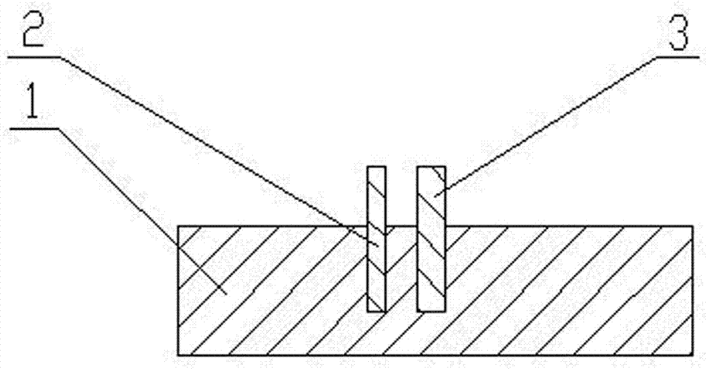
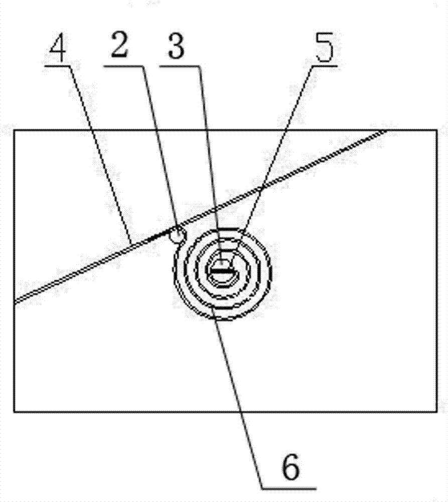
[0011] Referring to the accompanying drawings, a disc spring bending device includes a base 1 , a corner post 2 , and a post 3 for a disc spring. There are two circular blind holes in the middle of the upper end surface of the base 1, which are convenient for the insertion of the angled column 2 and the disc-shaped spring clamping column 3 and are fixed by the interference method. The position above the upper end surface of the protruding base 1 of the disc spring clip 3 is provided with a disc spring clamping groove 5, which is used for inserting and clamping the starting end of the core of the disc spring 6 when corners are bent. One end of the angled column 2 is inserted into the blind hole of the base 1 and fixed with an interference fit, and the other end of the angled column 2 protrudes from the upper end surface of the base 1 to locate t...


PUM


Abstract

The invention relates to a corner bending device for a disc spring. The corner bending device comprises a base, a spring clamping column and a corner bending column, the spring clamping column and the corner bending column are arranged on the upper portion of the base, a notch is formed in the top of the spring clamping column, the starting end of the center portion of a spring to be bent is clamped in the notch of the top of the spring clamping column, the corner bending column is arranged on one side of the spring clamping column, the distance between the corner bending column and the spring clamping column is matched with the distance between the corner bending position of the spring to be bent and the starting end of the center portion of the spring to be bent, the diameter of the corner bending column is matched with the diameter of the arc at the corner bent position of the spring. When the disc spring is processed, corner bending is carried out on the tail portion of the disc spring according to a certain length, a certain angle and a certain bending diameter to meet the manufacturing requirement and manufacturing precision of the disc spring, the processing size of the spring is guaranteed, and production efficiency and the qualified rate are improved.

Description

technical field [0001] The invention relates to a bending angle device of a disc spring. Background technique [0002] When producing a certain disc spring, the end of the spring is a hypotenuse at a certain angle, and there is a circular arc transition before the hypotenuse. The outermost tail of the disc spring should be bent according to a certain arc and a certain length, so as to ensure the installation size of the disc spring during the assembly process and improve the installation accuracy. At present, in actual production, the bends are clamped manually with pliers. In this way, the lengths and angles of the manually bent disk springs are not the same. The precision of the springs is not enough, which affects the installation, and some products have to be scrapped and remade. , low efficiency and high cost. Contents of the invention [0003] The object of the present invention is to overcome the above defects and provide a disc spring bending device to improve th...

Claims


Application Information

Patent Timeline
Patent Type & Authority Applications(China)
IPC IPC(8): B21F1/00B21F35/00
Inventor 李立元黄沌文徐伟文
Owner XIANGTAN ELECTRIC MFG
Why Eureka
Try Eureka