CNC Welding Bed for Realizing NC Welding of Plane Convex Weld

A convex profile and flat technology, applied in welding equipment, auxiliary welding equipment, welding/cutting auxiliary equipment, etc., can solve the problems of lack of real-time adjustment mechanism of welding torch, unable to meet the requirements of curved seam welding process, etc., to meet the welding process requirements. desired effect

Active Publication Date: 2016-01-20
BEIJING POLYTECHNIC
View PDF9 Cites 0 Cited by
  • Summary
  • Abstract
  • Description
  • Claims
  • Application Information

AI Technical Summary

Problems solved by technology

[0003] However, the current welding bed only has the function of X-axis, Y-axis and Z-axis three-axis linkage. Although the three-axis linkage can generate a curved trajectory, because this welding bed has a welding torch attitude control axis, this welding torch attitude control axis There is no real-time adjustment mechanism for the attitude angle of the welding torch, so from the perspective of the welding bed mechanism, it cannot meet the welding process requirements of the curved welding seam

Method used


Image

  • CNC Welding Bed for Realizing NC Welding of Plane Convex Weld
  • CNC Welding Bed for Realizing NC Welding of Plane Convex Weld
  • CNC Welding Bed for Realizing NC Welding of Plane Convex Weld

Examples


Embodiment Construction

[0013] The present invention will be described in further detail below through specific implementation examples and in conjunction with the accompanying drawings.

[0014] Plane convex profile definition: such as Figure 5 As shown, a contour line V on the plane, if there is a point O on the plane, and any ray S is made on the plane through point O, if any ray S has at most one intersection point with the contour line V, then the contour line V is called a plane convex profile. It is called the center of gyration of the plane convex profile at point O. The straight line passing through O and perpendicular to the plane of the contour line V is called the axis of rotation. A planar convex profile may have an infinite number of centers of revolution and therefore an infinite number of axes of revolution at the same time.

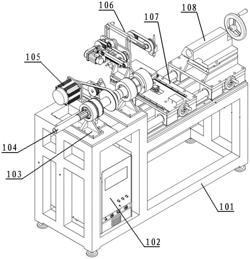
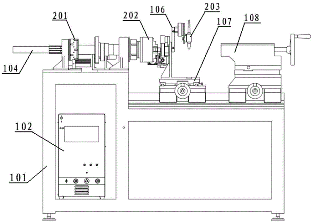
[0015] Such as figure 1 with figure 2 Shown is a numerically controlled welding bed for realizing numerically controlled welding of planar convex contour...


PUM


Abstract

The invention relates to the field of mechanical devices, in particular to a numerical control welding lathe for achieving numerical control welding of a planar convex profile welding seam. The numerical control welding lathe for achieving numerical control welding of the planar convex profile welding seam comprises an A axis which controls a workpiece to be welded to rotate around an X axis, a Y axis and an A' axis which controls a welding gun to rotate around the welding tip of the welding gun. According to the numerical control welding lathe, compared with a welding lathe in the prior art, the attitude angle of the welding gun can be adjusted in real time in the moving process along the welding seam according to the curvature change of the welding seam, and therefore the welding technological requirement is met.

Description

technical field [0001] The invention relates to the field of mechanical devices, in particular to a numerically controlled welding bed for realizing numerically controlled welding of planar convex contour welds. Background technique [0002] The current industrial welding bed includes X-axis, Y-axis and Z-axis. Specifically, the X axis is used to control the movement of the welding torch along the X axis, the Y axis is used to control the movement of the welding torch along the Y axis, and the Z axis is used to control the movement of the welding torch along the Z axis. When the welding bed is used to weld the workpiece, the X-axis, Y-axis and Z-axis are linked to control the welding torch, so that the welding torch runs along the track of the weld seam to achieve the purpose of welding the weld seam. [0003] However, the current welding bed only has the function of X-axis, Y-axis and Z-axis three-axis linkage. Although the three-axis linkage can generate a curved trajecto...

Claims


Application Information

Patent Timeline
Patent Type & Authority Patents(China)
IPC IPC(8): B23K37/02B23K37/047
CPCB23K37/0252B23K37/0426
Inventor 李书田刘京华李海霞顾春光甄雪松
Owner BEIJING POLYTECHNIC
Why Eureka
Try Eureka