Elastic manipulator with part protection structure

A technology of manipulators and parts, which is applied in the field of manipulators, can solve the problems of large force and damage of parts to be grasped, and achieve the effect of improving the efficiency of grasping

Inactive Publication Date: 2014-03-05
CHONGQING FENGGUO QIYANG TECH DEV
View PDF0 Cites 29 Cited by
  • Summary
  • Abstract
  • Description
  • Claims
  • Application Information

AI Technical Summary

Problems solved by technology

[0004] Aiming at the defects in the above-mentioned prior art, the technical problem to be solved by the present invention is: the existing manipulator claw is connected with the piston rod of the cylinder through a transmission structure such as a connecting ro

Method used


Image

  • Elastic manipulator with part protection structure

Examples


Embodiment Construction

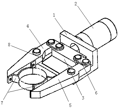
[0011] like figure 1 As shown, an elastic manipulator with a protective part structure includes a base 1, a cylinder 2, a drive block 3, a first gripper 4, a second gripper 5 and a connecting rod 6, and the cylinder 2 is arranged on the base 1. The first claw 4 and the second claw 5 are located on both sides of the drive block 3, and both middle parts are hinged on the base 1, and the first claw 4 and the second claw 5 are connected to the drive block at one end near the cylinder 2 3 is hinged through the connecting rod 6, and the distance between the hinged ends of the first claw 4 and the second claw 5 is the largest limit position where the drive block 3 moves, and the drive block 3 is connected to the piston rod of the cylinder 2. Spring plates 7 are respectively arranged at the relative positions of the gripping sides of the gripper 4 and the second gripper 5, and the two ends of the spring gripper 7 are fixed, and there is a gap between the gripping part in the middle an...


PUM


Abstract

The invention relates to a manipulator, in particular to an elastic manipulator with a part protection structure. The elastic manipulator comprises a base, an air cylinder, a driving block, a first claw, a second claw and connecting rods, the air cylinder is arranged on the base, the first claw and the second claw are located on two sides of the driving block, middles of the first claw and the second claw are both hinged to the base, one end, close to the air cylinder, of each of the first claw and the second claw is hinged to the driving block through the corresponding connecting rod, the driving block is connected with a piston rod of the air cylinder, spring plates are arranged at opposite positions of clamping sides of the first claw and the second claw, two ends of each spring plate are fixed, and a gap is formed between the middle clamping portion of each spring plate and the inner side of the corresponding claw. When the elastic manipulator is used for grabbing parts, the spring plates with elasticity are in contact with the parts, and the elastic faces can protect the parts.

Description

technical field [0001] The invention relates to a manipulator, in particular to an elastic manipulator with a structure for protecting parts. Background technique [0002] The manipulator can imitate certain action functions of the human hand, and is used to grasp and carry objects or operate automatic operation devices according to a fixed program. The manipulator is the earliest industrial robot and the earliest modern robot. It can replace the heavy labor of human beings to realize the mechanization and automation of production, so it is widely used in machinery manufacturing, metallurgy, electronics, light industry and atomic energy and other departments. Manipulator drive methods can be divided into hydraulic, pneumatic, electric, and mechanical, among which pneumatic manipulators driven by cylinders are the most common. [0003] The gripper of a general manipulator is connected to the piston rod of the cylinder through a transmission structure such as a connecting rod...

Claims


Application Information

Patent Timeline
IPC IPC(8): B25J15/08
Inventor 姜静慧
Owner CHONGQING FENGGUO QIYANG TECH DEV
Why Eureka
Try Eureka