Eureka AIR delivers breakthrough ideas for toughest innovation challenges, trusted by R&D personnel around the world.

Automatic blank fetching equipment

An automatic and equipment technology, applied in the stacking of objects, de-stacking of objects, conveyors, etc., can solve the problems of reducing production efficiency, wasting blank disk space, and low degree of automation, so as to improve the degree of automation and improve production. Efficient and practical effect

Inactive Publication Date: 2014-03-05
HANGZHOU DONGBO AUTOMATION SCI & TECH
View PDF8 Cites 16 Cited by
  • Summary
  • Abstract
  • Description
  • Claims
  • Application Information

AI Technical Summary

Problems solved by technology

[0004] The above scheme reduces the labor intensity to a certain extent, but the scheme also has at least the following defects: the design is unreasonable, and the stacking of the blank trays cannot be realized, that is to say, when the blanks are full of one blank tray, The transmission component transmits the blank disk, and each output blank disk is stacked by machinery or people, which not only reduces the production efficiency, but also is labor-intensive and has a low degree of automation; in addition, in When placing the blank after taking the blank, the distance between the blanks placed on the blank disk is equal to the distance in the mold, which not only wastes the space of the blank disk, but also reduces the production efficiency to a certain extent, and has poor practicability. Meet the development requirements of the enterprise

Method used


Image

  • Automatic blank fetching equipment
  • Automatic blank fetching equipment
  • Automatic blank fetching equipment

Examples


Embodiment Construction

[0039] The present invention will be described in further detail below in conjunction with the accompanying drawings and specific embodiments.

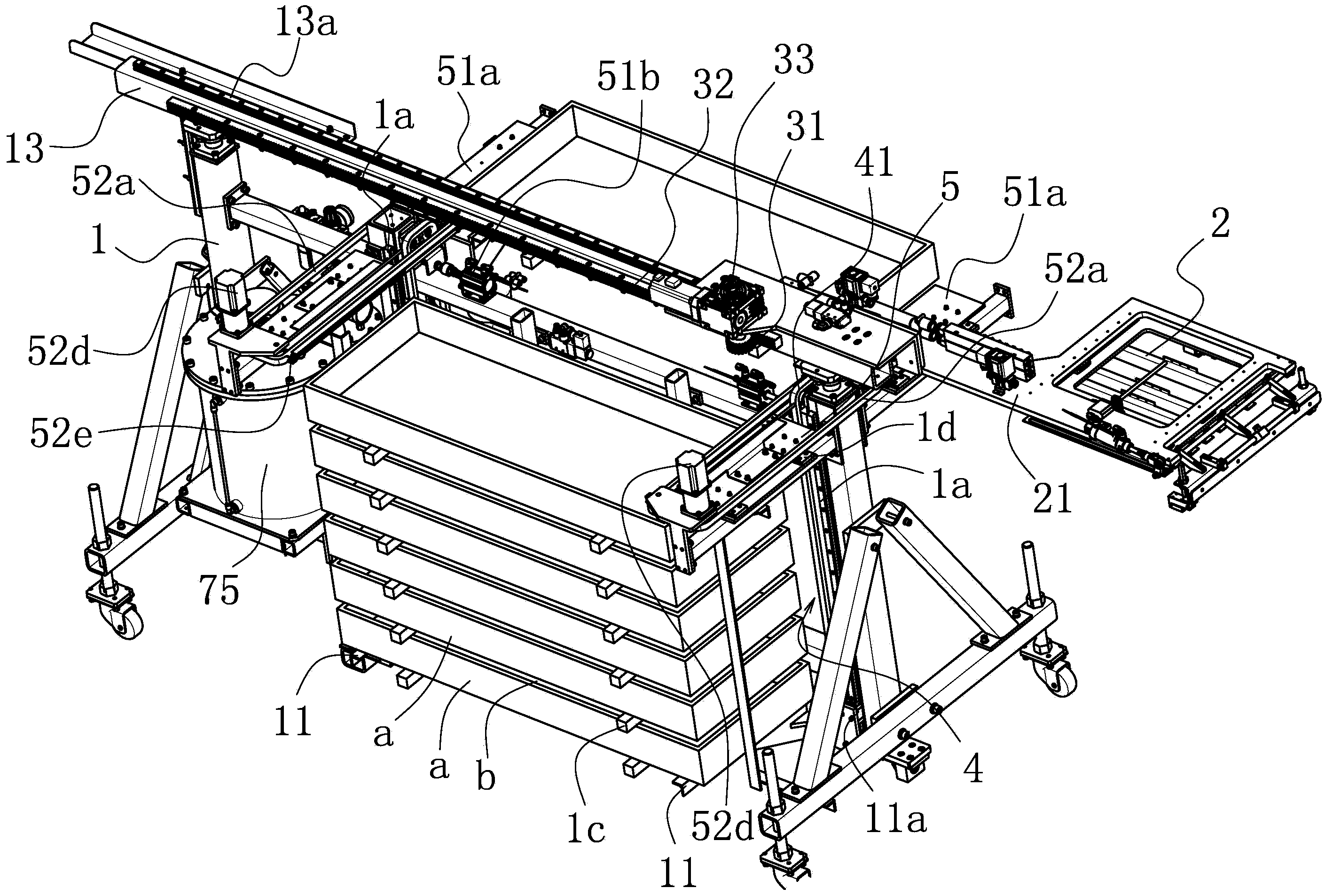
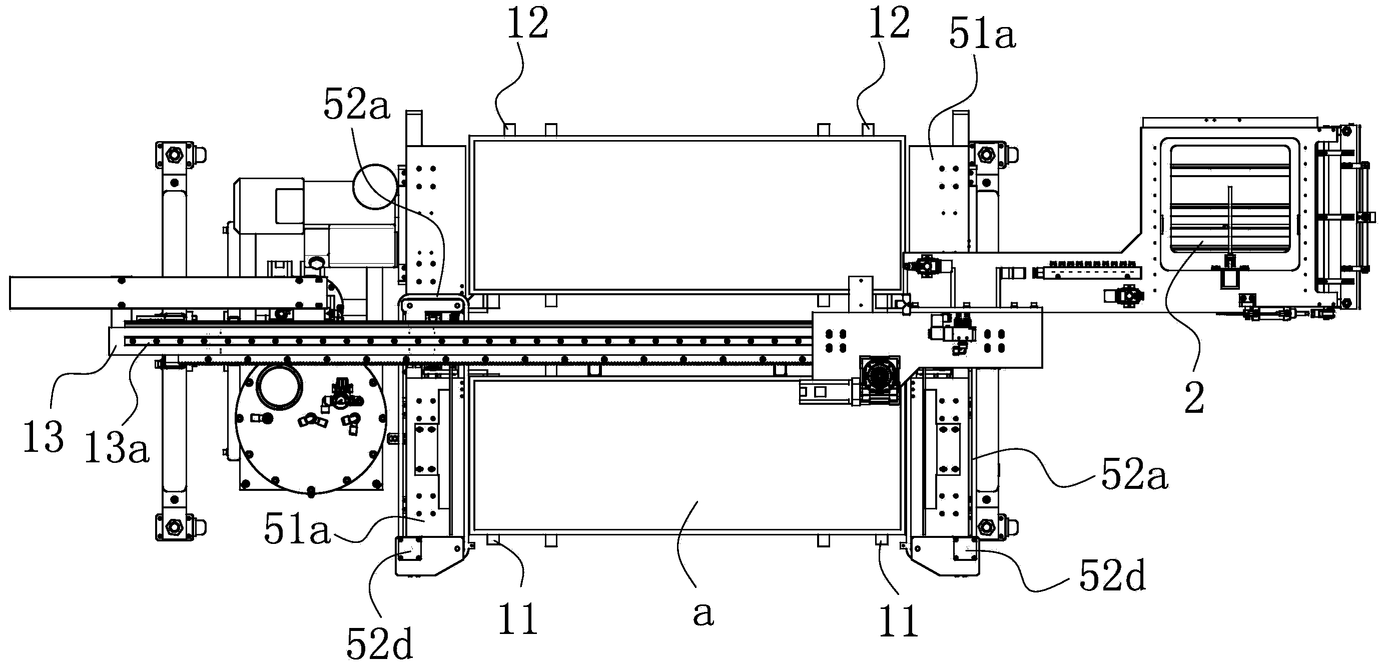
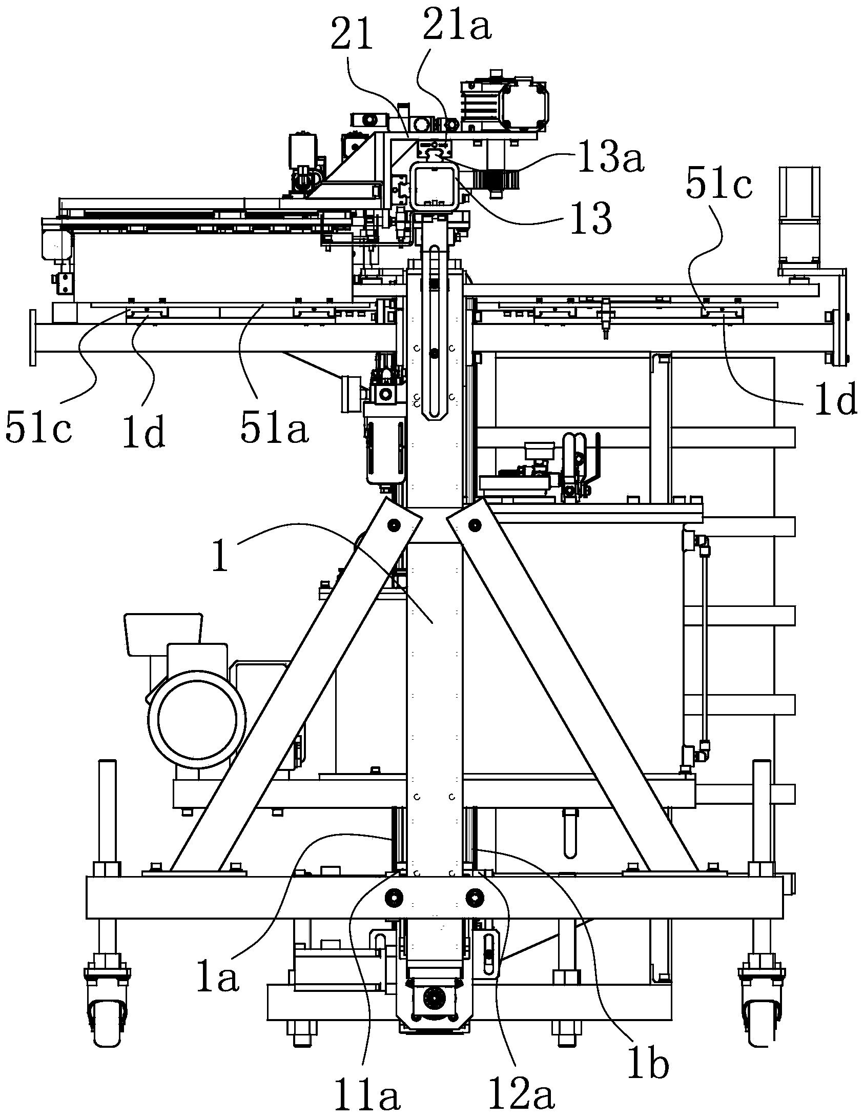
[0040] Such as Figure 1-7 As shown, the automatic billet removal equipment includes a frame 1, on which a manipulator 2 is arranged, and between the frame 1 and the manipulator 2, a longitudinal axis capable of driving the manipulator 2 to reciprocate and translate along the longitudinal direction of the frame 1 is provided. The translational drive mechanism 3 is provided with a tray delivery lifter 11 and a pick-up lifter 12 on both sides of the frame 1 respectively, and the blank tray a stacked on the pick-up lifter 12 is located in the longitudinal direction of the manipulator 2. Below the translation track, the frame 1 is provided with a device that is respectively connected to the tray sending elevator 11 and the tray receiving elevator 12 and can drive the tray sending elevator 11 and the tray receiving elevator 12 to move sync...


PUM


Abstract

The invention belongs to the technical field of mechanical equipment, in particular to automatic blank fetching equipment. The automatic blank fetching equipment solves the technical problems that practicality is poor in the prior art. The automatic blank fetching equipment comprises a rack, a mechanical arm is arranged on the rack, a longitudinal translation driving mechanism capable of driving the mechanical arm to shift horizontally and repeatedly in the longitudinal direction of the rack is arranged between the rack and the mechanical arm, a disc sending lifting frame and a disc receiving lifting frame used for stacking blank discs are arranged on the two sides of the rack respectively, and blank discs stacked on the disc receiving lifting frame are located below the longitudinal translation track of the mechanical arm. A lifting driving device is arranged on the rack, wherein the lifting driving device is respectively connected to the disc sending lifting frame and the disc receiving lifting frame, and can drive the disc sending lifting frame and the disc receiving lifting frame to carry out synchronous reversed lifting motion on the two sides of the rack. A disc conveying device capable of enabling the top blank disc to be conveyed to the side, where the disc receiving lifting frame is located, of the rack from the side where the disc sending lifting frame is located, of the rack is further arranged on the rack. Compared with the prior art, the automatic blank fetching equipment has the advantage of being high in automation degree.

Description

technical field [0001] The invention belongs to the technical field of mechanical equipment, and in particular relates to an automatic billet-taking equipment. Background technique [0002] With the continuous innovation of science and technology, in the field of machinery manufacturing, in order to improve production efficiency, many current enterprises generally conduct independent research and development or use mechanical automation equipment for production operations, which not only improves production efficiency, but also reduces The labor intensity is reduced. For example, in the mechanical equipment of the magnetic material industry, the magnetic material is generally formed by a press. The press is equipped with a static mold and a dynamic mold. After the pressing is completed, the billet is manually removed, and then Stacking, this scheme can meet the production requirements to a certain extent; but this scheme not only has low production efficiency and automation,...

Claims


Application Information

Patent Timeline
Patent Type & Authority Applications(China)
IPC IPC(8): B65G47/91B65G61/00B65G19/02
Inventor 沈军民
Owner HANGZHOU DONGBO AUTOMATION SCI & TECH
Why Eureka
Eureka Blog
Learn More