Stiff framework and method for constructing bridge tower column by means of same

A technology of rigid skeleton and bridge tower, which is applied in the direction of erecting/assembling bridges, bridges, bridge parts, etc., can solve the problems of increasing construction cost, large consumption of section steel, and reducing construction quality, so as to increase stability and consumption of section steel Low, the effect of reducing construction costs

Active Publication Date: 2014-03-05
SHANGHAI MUNICIPAL CONSTR
View PDF6 Cites 26 Cited by
  • Summary
  • Abstract
  • Description
  • Claims
  • Application Information

AI Technical Summary

Problems solved by technology

[0004] For the existing tower column construction, the stiff frame is set inside the tower column, which consumes a lot of steel, and the concrete inside the tower column is prone to cracks along the direction of the stiff frame, which not only increases the construction cost, but also reduces the construction quality. Problem, the object of the present invention is to provide a stiff skeleton and a method for using it to construct a bridge tower column. The stiff skeleton is arranged outside the tower column, and the components in the stiff skeleton can be reused, which not only reduces the It also avoids cracks in the concrete of the tower column and improves the construction quality

Method used


Image

  • Stiff framework and method for constructing bridge tower column by means of same
  • Stiff framework and method for constructing bridge tower column by means of same
  • Stiff framework and method for constructing bridge tower column by means of same

Examples


Embodiment Construction

[0032] A stiff skeleton proposed by the present invention and a method for using it to construct bridge towers will be further described below in conjunction with the accompanying drawings and specific embodiments. Advantages and features of the present invention will be apparent from the following description and claims. It should be noted that all the drawings are in a very simplified form and use imprecise scales, and are only used to facilitate and clearly assist the purpose of illustrating the embodiments of the present invention.

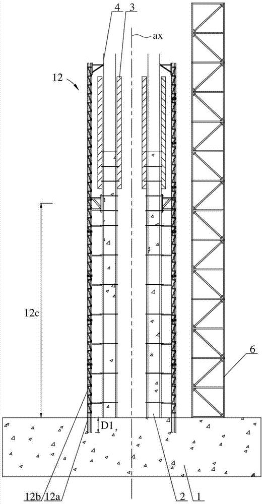
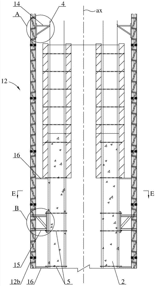
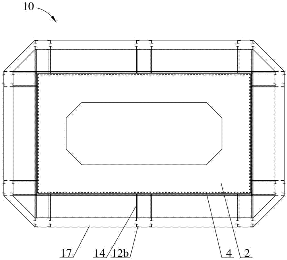
[0033] combine Figure 1 to Figure 5 The rigid framework 10 of the present invention is illustrated, it comprises:

[0034] At least two skeleton bodies 12 enclosed on the outside of the tower column 2;

[0035] Several cross bars 16 are used to connect the framework main body 12 and the pillar 2;

[0036] And at least two steel bar positioning support arm devices 14 connected to the skeleton main body 12 for positioning the main bars 4 in ...


PUM


Abstract

The invention provides a stiff framework and a method for constructing a bridge tower column by means of the stiff framework, and relates to the technical field of methods for erecting or assembling bridges. The problems that an existing stiff framework is arranged in a tower column, structural steel consumption is high and concrete in the tower column easily cracks are resolved. The stiff framework comprises framework main bodies enclosing the outer side of the tower column, a plurality of transverse rods and a steel bar positioning supporting arm device; each framework main body is composed of a stiff framework pre-buried section and a plurality of stiff framework standard sections, and multiple stiff framework standard sections connected in a head-to-end mode along the axis form a stiff framework unit. The method comprises the steps that firstly, the stiff framework pre-buried sections and the standard sections are prefabricated; secondly, a formwork and the framework main bodies are erected, and main reinforcement is positioned through the steel bar positioning supporting arm device; thirdly, the formwork and the framework main bodies continue to be erected, then the main reinforcement is positioned through the steel bar positioning supporting arm device, and the formwork and the framework main bodies are disassembled after being constructed; fourthly, the tower column is fixedly connected with the transverse rods through the stiff framework standard sections; the third step and the fourth step are repeated, and the stiff framework is disassembled after pouring is completed.

Description

technical field [0001] The invention relates to the technical field of methods for erecting or assembling bridges, in particular to a stiff skeleton and a method for using the stiff skeleton to construct bridge towers. Background technique [0002] Long-span cable-stayed bridges and suspension bridges are high-order statically indeterminate structural systems with high tower columns and large girder spans. In order to ensure the quality and safety of tower column construction, it is the most common way to use stiff skeleton to assist construction. The traditional rigid frame is generally a steel truss structure with high rigidity composed of three parts: frame columns, frame cross bars and frame diagonal bars. It is the supporting frame for the positioning of the main reinforcement skeleton of the tower column and the adjustment of the inner and outer molds. During the installation process of the main reinforcement framework, the rigid framework is used to correct the devi...

Claims


Application Information

Patent Timeline
Patent Type & Authority Applications(China)
IPC IPC(8): E01D21/00E01D19/14
Inventor 宋胜录秦雨春顾国平周智科高超
Owner SHANGHAI MUNICIPAL CONSTR
Why Eureka
Try Eureka