Mine gas bundle pipeline monitoring system

A monitoring system and beam tube technology, applied in mining equipment, mining equipment, earthwork drilling and mining, etc., can solve problems such as difficulty in finding pipeline fault points, low overall efficiency, safety accidents, etc., and achieve improved usability, reliability, and accuracy The scope of pipeline faults and the effect of ensuring safe production

Active Publication Date: 2015-05-20
CCTEG SHENYANG RES INST +2
View PDF4 Cites 0 Cited by
  • Summary
  • Abstract
  • Description
  • Claims
  • Application Information

AI Technical Summary

Problems solved by technology

The fault of the pipeline can be qualitatively identified through the change of the ground pressure gauge, but it is very difficult to find the fault point of the pipeline. Maintenance personnel need to search the bundled pipeline from the beginning to the end. Generally, the length of the bundled pipeline is more than ten kilometers , the large number of pipelines is time-consuming and laborious to maintain, and the overall efficiency is low, which affects the real-time monitoring of coal mine gas by the mine gas bundle tube monitoring system, and may cause safety accidents

Method used


Image

  • Mine gas bundle pipeline monitoring system
  • Mine gas bundle pipeline monitoring system
  • Mine gas bundle pipeline monitoring system

Examples


no. 1 example

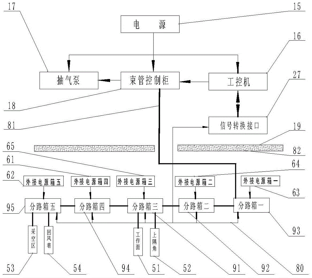
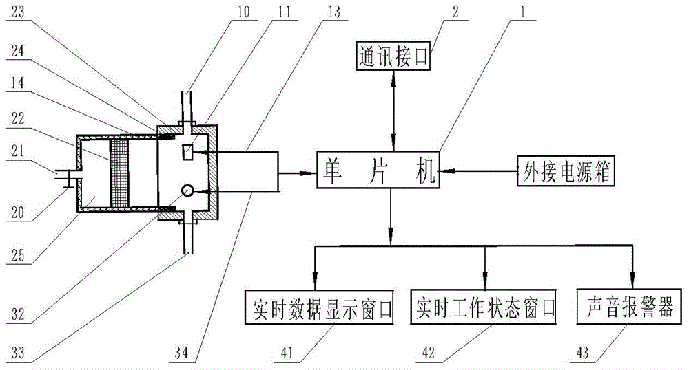
[0030] For a first example, see figure 1 , figure 2 , a mine gas bundle pipe pipeline monitoring system, which includes a power supply 15 electrically connected to an air pump 17 on the ground 19, a PLC programmable control bundle pipe control cabinet 18, and an industrial computer 16, characterized in that: the industrial computer 16 is electrically connected to signal conversion Interface 27, PLC programmable control beam tube control cabinet 18 tubes connected underground 82 equipped with external power box 1 63, external power box 2 64, external power box 3 65, external power box 4 61, external power box 5 62 Branch box one 93, branch box two 92, branch box three 91, branch box four 94, branch box five 95, signal conversion interface 27 is connected to the communication interface 2 of each branch box by system communication line 80. The number of branch boxes and the number of external power supply boxes are determined according to actual needs.

[0031] Wherein: the sh...

no. 2 example

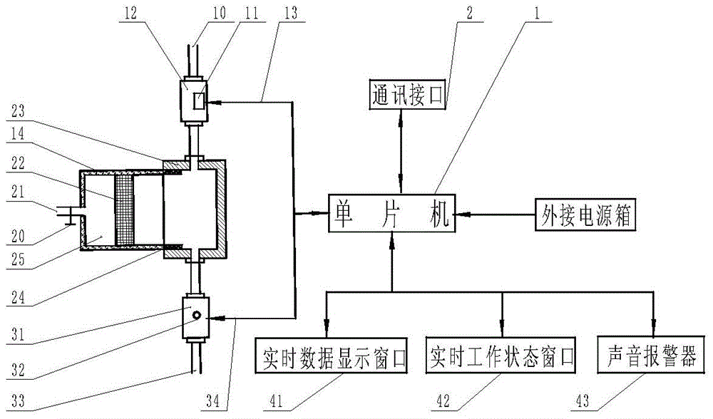
[0036] For a second embodiment, see figure 1 , image 3 , a mine gas bundle pipe pipeline monitoring system, which includes a power supply 15 electrically connected to an air pump 17 on the ground 19, a PLC programmable control bundle pipe control cabinet 18, and an industrial computer 16, characterized in that: the industrial computer 16 is electrically connected to signal conversion Interface 27, PLC programmable control beam tube control cabinet 18 tubes connected underground 82 equipped with external power box 1 63, external power box 2 64, external power box 3 65, external power box 4 61, external power box 5 62 Branch box one 93, branch box two 92, branch box three 91, branch box four 94, branch box five 95, signal conversion interface 27 is connected to the communication interface 2 of each branch box by system communication line 80. The number of branch boxes and the number of external power supply boxes are determined according to actual needs.

[0037] Wherein: the...


PUM


Abstract

The invention relates to a mine gas bundle pipe pipeline monitoring system, which includes a power supply on the ground electrically connected to an air pump, a PLC programmable control bundle pipe control cabinet, and an industrial computer. Controlled bundle tube control cabinet The bundle tube is connected to several branch boxes equipped with external power supply boxes in the underground, and the signal conversion interface is connected to the communication interface of several branch boxes by the system communication line. Combine monitoring methods. Ensure the timely and effective troubleshooting of the tube tube failure, improve the availability and reliability of the mine gas tube tube monitoring system, and greatly reduce the troubleshooting scope of the tube tube tube. The real-time data and working status displayed in the display window and the real-time working status window can accurately determine the nature and specific location of the pipeline failure.

Description

Technical field [0001] The invention relates to a coal mine underground gas bundle pipe monitoring system, in particular to a mine gas bundle pipe pipeline monitoring system. Background technique [0002] At present, the gas analysis method is mainly used to predict spontaneous combustion in underground coal mines at home and abroad. The main form of realization is to use the mine gas bundle tube monitoring system, which can also provide the basis for gas prevention and control. It has been popularized and widely used in my country's coal mines. Carry out conventional forecasting and forecasting in production mines, and serve disaster relief during mine disaster relief. The basic principle is to lay multi-channel bundle pipes from the ground to the monitoring sites such as coal mining work sites or goafs, and use a vacuum pump to pump the sampling gas to the ground gas chromatograph for gas component analysis. According to CO, CH 4 、C 2 h 4 , O 2 It can also be used to ...

Claims


Application Information

Patent Timeline
Patent Type & Authority Patents(China)
IPC IPC(8): E21F17/18
Inventor 梁运涛肖开泰郝贵冯文彬张光德周勇杨波田富超张伟杰
Owner CCTEG SHENYANG RES INST
Why Eureka
Try Eureka