A rotary core type circumferential flow distribution device for a reciprocating plunger pump

A plunger pump and plunger technology, which is applied in the field of rotary core type circumferential flow distribution device for reciprocating plunger pumps, can solve the problems of large pressure loss, high cost, and large volume

Inactive Publication Date: 2016-02-17
QINGDAO UNIV
View PDF5 Cites 0 Cited by
  • Summary
  • Abstract
  • Description
  • Claims
  • Application Information

AI Technical Summary

Problems solved by technology

[0003] The purpose of the present invention is mainly to overcome the shortcomings of low volume efficiency, large pressure loss, large volume and high cost of the traditional flow distribution system for reciprocating plunger pumps, and to seek a low cost, compact structure, small pressure loss, high volume efficiency and stable performance. The rotary core type circumferential flow distribution device for reciprocating plunger pumps realizes the conversion and output of mechanical energy to hydraulic energy

Method used


Image

  • A rotary core type circumferential flow distribution device for a reciprocating plunger pump
  • A rotary core type circumferential flow distribution device for a reciprocating plunger pump
  • A rotary core type circumferential flow distribution device for a reciprocating plunger pump

Examples


Embodiment

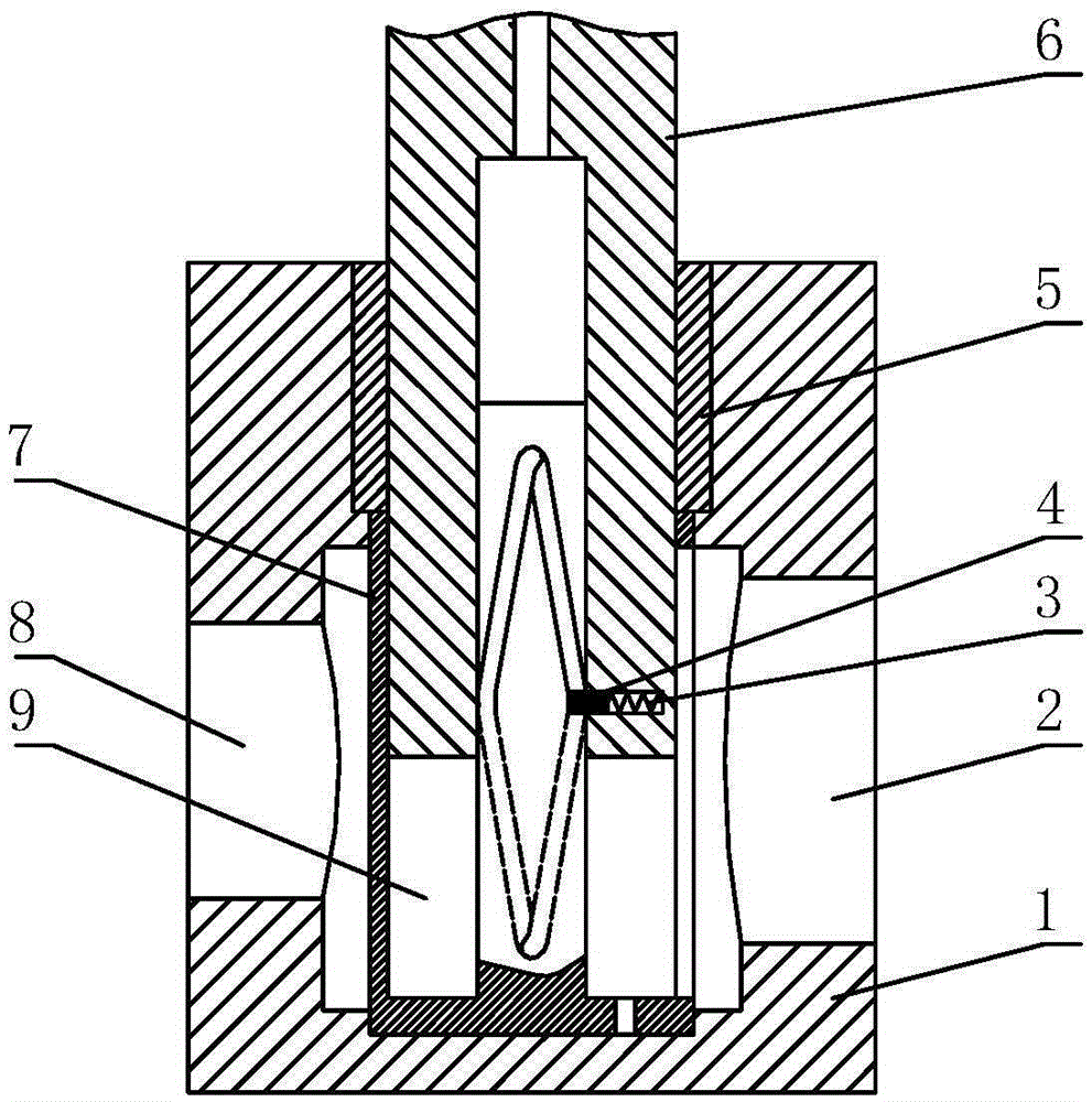
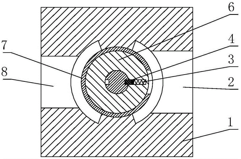
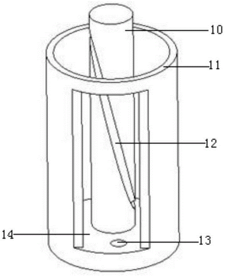
[0013] The main structure of the present embodiment is a pump body 1, a fluid inlet 2, a compression spring 3, a driven pin 4, a sliding sleeve 5, a plunger 6, a valve core 7, a fluid outlet 8 and a pump chamber 9, wherein the valve core 7 includes a valve core Center shaft 10, spool peripheral wall 11, cam groove 12, spool hole 13 and distribution hole 14; the shape of the pump body 1, which plays a supporting and connecting role, is designed according to the environment and equipment requirements of the pump body 1; the hollow cylindrical structure The plunger 6 is fixedly installed in the cavity of the pump body 1, and the sliding sleeve 5 made of wear-resistant or self-lubricating material is embedded in the pump body 1 to guide the plunger 6; the sliding sleeve 5 and the plunger 6 Close fit, the plunger 6 reciprocates in the axial direction in the sliding sleeve 5 under the action of external force; the circular inner cavity of the plunger 6 is provided with air holes comm...


PUM


Abstract

The invention belongs to the technical field of hydraulic power transfer and output equipment, and relates to a rotary core type circumferential flow distribution device for a reciprocating plunger pump. A plunger is fixedly mounted in a cavity of a pump body; a slide sleeve is mounted in the pump body; an air hole is formed in the inner cavity of the plunger; a radial small hole is formed in the inner side wall of the plunger; a pressure spring and a driven pin are arranged on the radial small hole; a valve core is mounted below the slide sleeve; the outer surface of the valve core is the circumferential wall of the valve core; a circular cavity formed between the central shaft of the valve core and the circumferential wall of the valve core and the lower end surface of the plunger form a pump cavity; a valve core hole is formed in the lower end surface of the valve core; a cam groove is formed on the central shaft of the valve core; a flow distribution hole is formed in the circumferential wall of the valve core; a liquid inlet is formed on the right of the circumferential wall of the valve core, and a liquid outlet is formed on the left; the valve core, the cam groove on the outer circle surface of the central shaft of the valve core, the driven pin and the plunger form a deformation translation cylindrical guide groove cam mechanism. The device provided by the invention has the advantages of compact structure, high volume efficiency, stable performance, low pressure loss, good energy saving effect, wide application range and broad industrialization prospect.

Description

Technical field: [0001] The invention belongs to the technical field of hydraulic power transmission and output equipment, and relates to a rotary core type circumferential flow distribution device for a reciprocating plunger pump. Background technique: [0002] The pump industry consumes about 20% of electric energy, and it is the second largest electromechanical industry after automobiles in the world. Among them, reciprocating plunger pumps are widely used in fluid engines, crude oil transportation, gas stations, pump stations, mobile machinery and stationary machinery . At present, the most serious problem of the reciprocating plunger pump is that the structure of the distribution system is loose and large, the efficiency is low, and the performance is unstable. The existing distribution structure has two types: disc distribution and valve distribution. On inclined-axis hydraulic motors or hydraulic pumps, disc-type flow distribution is not used on reciprocating plunger...

Claims


Application Information

Patent Timeline
Patent Type & Authority Patents(China)
IPC IPC(8): F04B53/14
Inventor 张洪信杨道斋舒培张铁柱尹怀仙马永志
Owner QINGDAO UNIV
Why Eureka
Try Eureka