Energy recovery hydraulic system and engineering machine

A hydraulic system and energy recovery technology, applied in the hydraulic field, can solve problems such as high cost, poor adaptability, and complex control, and achieve the effects of simple and convenient control, good real-time performance, and simple structure

Inactive Publication Date: 2014-03-05
SANY AUTOMOBILE MFG CO LTD
View PDF6 Cites 23 Cited by
  • Summary
  • Abstract
  • Description
  • Claims
  • Application Information

AI Technical Summary

Problems solved by technology

[0007] In view of this, the present invention proposes an energy recovery hydraulic system. The energy recovery hydraulic system can not only realize energy recovery, but also solve the problem of poor real-time energy recovery, complicated control, and poor adaptabi

Method used


Image

  • Energy recovery hydraulic system and engineering machine
  • Energy recovery hydraulic system and engineering machine
  • Energy recovery hydraulic system and engineering machine

Examples


Embodiment Construction

[0026] It should be noted that, in the case of no conflict, the embodiments of the present invention and the features in the embodiments can be combined with each other. The following will refer to the attached Figure 2-6 The present invention will be described in detail in combination with examples.

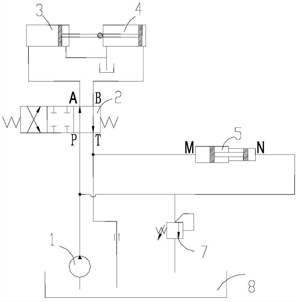
[0027] Such as figure 2 As shown, the specific embodiment of the present invention proposes an energy recovery hydraulic system, including a pressure oil source, an oil tank 8, a reversing valve 2, an actuator and a booster device, wherein the pressure oil source is a hydraulic pump 1, and the reversing valve 2 is a three-position four-way valve, including oil port P (first oil port), oil port A (second oil port), oil port T (third oil port) and oil port B (fourth oil port). Port P is connected with the oil outlet of hydraulic pump 1, oil port A and oil port B are connected with the actuator, oil port T is connected with oil tank 8, and the low pressure end of the booster de...


PUM


Abstract

The invention discloses an energy recovery hydraulic system which comprises a pressure oil source, an oil tank, a reversing valve, an actuator and a supercharging device. The supercharging device is arranged in a hydraulic oil line, the two ends of the supercharging device are directly connected between an oil inlet line and an oil outlet line, the two ends of the supercharging device are not connected with control valves, that is the low-pressure end of the supercharging device is communicated with an oil line between a third oil port of the reversing valve and the oil tank, and the high-pressure end of the supercharging device is communicated with an oil line between the pressure oil source and a first oil port of the reversing valve, and therefore operation of the supercharging device does not need to be controlled by a control valve. The energy recovery hydraulic system can be used for recycling energy at any time and is good in energy recycling instantaneity, simple in structure, easy and convenient to control, and low in cost. Besides, the invention further discloses an engineering machine provided with the energy recovery hydraulic system and pumping equipment provided with the energy recovery hydraulic system.

Description

technical field [0001] The invention relates to the field of hydraulic technology, in particular to an energy recovery hydraulic system and construction machinery equipped with the energy recovery hydraulic system. Background technique [0002] At present, energy recovery pneumatic and hydraulic systems are generally used in braking systems and energy conversion systems, such as automobile braking systems, crane jib potential energy recovery systems, etc. Most of the prior art utilizes accumulators to recover system energy, and the accumulators are controlled by a control valve group. [0003] Specifically, Chinese patent No. "201210025010.1" discloses a hydraulic transmission that allows energy recovery, such as figure 1 As shown, the hydraulic transmission device mainly includes a hydraulic motor 101, a hydraulic pump 100, a fluid accumulator 102, a plurality of electromagnetic reversing valves and actuators, the hydraulic pump 100 provides the power source, the electroma...

Claims


Application Information

Patent Timeline
IPC IPC(8): F15B21/14F15B3/00F15B1/02
Inventor 黎桑陈城曾斌
Owner SANY AUTOMOBILE MFG CO LTD
Why Eureka
Try Eureka