Cutting insert, cutting tool, and method for manufacturing cut product using cutting tool

A technology for cutting inserts and cutting tools, used in milling cutting inserts, manufacturing tools, accessories of tool holders, etc., can solve the problems of long elongation and surface quality degradation, and achieve the effect of excellent chip discharge.

Active Publication Date: 2014-03-05
KYOCERA CORP
View PDF5 Cites 11 Cited by
  • Summary
  • Abstract
  • Description
  • Claims
  • Application Information

AI Technical Summary

Problems solved by technology

[0003] However, in the insert in Japanese Patent Application Laid-Open No. 11-333616, such Figure 7 etc., the rake surfaces 35, 36 at the positions corresponding to the main cutting edges 24, 25 are planar surfaces, therefore, the chips generated by the main cutting edges 24, 25 move along the main cutting edges 24, 25 In the state of inclined shape, the chips are discharged through the planar rake surfaces 35, 36, therefore, the chips are stable and difficult to curl, which may result in longer elongation.
As a result, chips are bitten between the insert and the workpiece, which may degrade the surface quality of the machined surface of the workpiece

Method used


Image

  • Cutting insert, cutting tool, and method for manufacturing cut product using cutting tool
  • Cutting insert, cutting tool, and method for manufacturing cut product using cutting tool
  • Cutting insert, cutting tool, and method for manufacturing cut product using cutting tool

Examples


no. 1 approach )

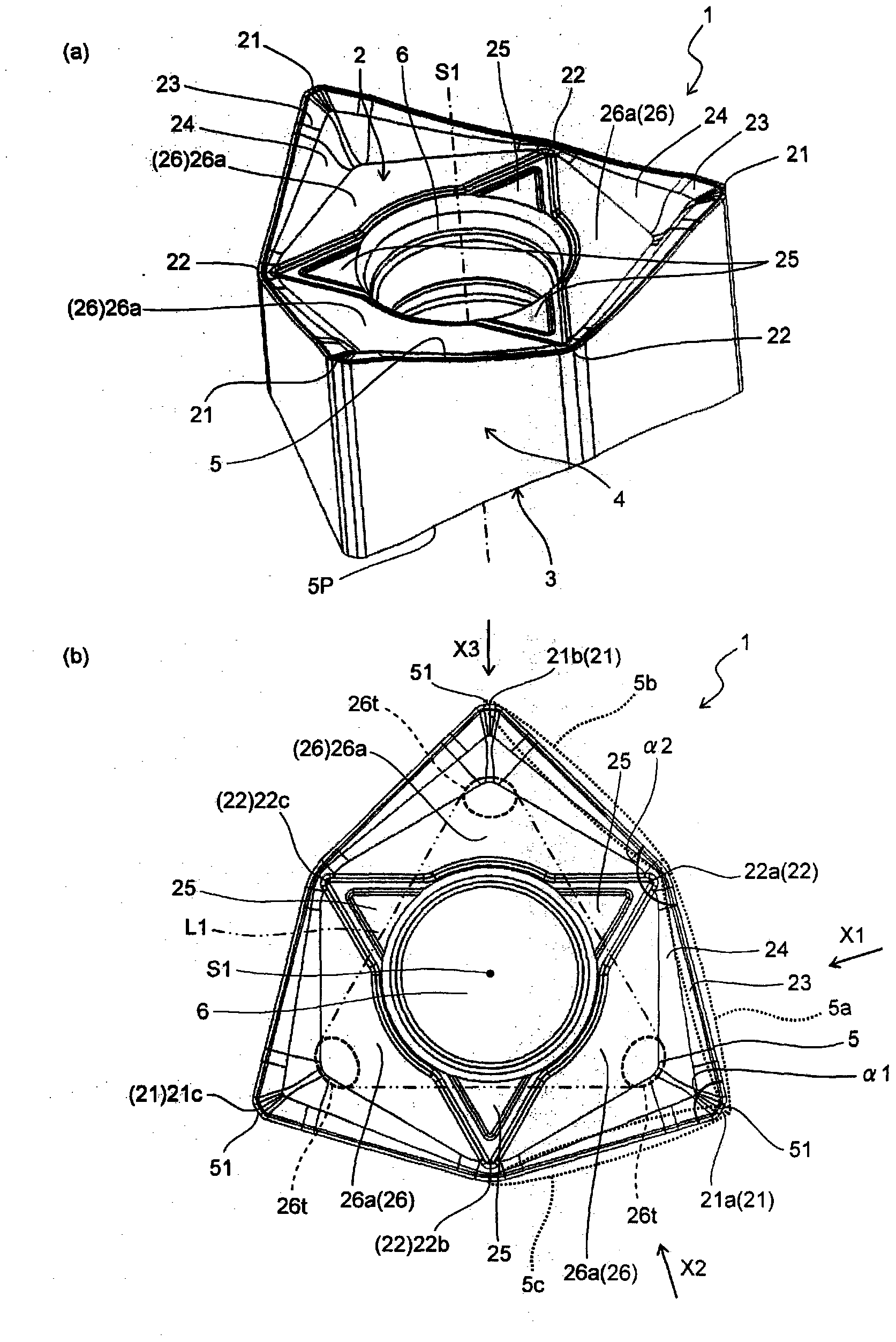
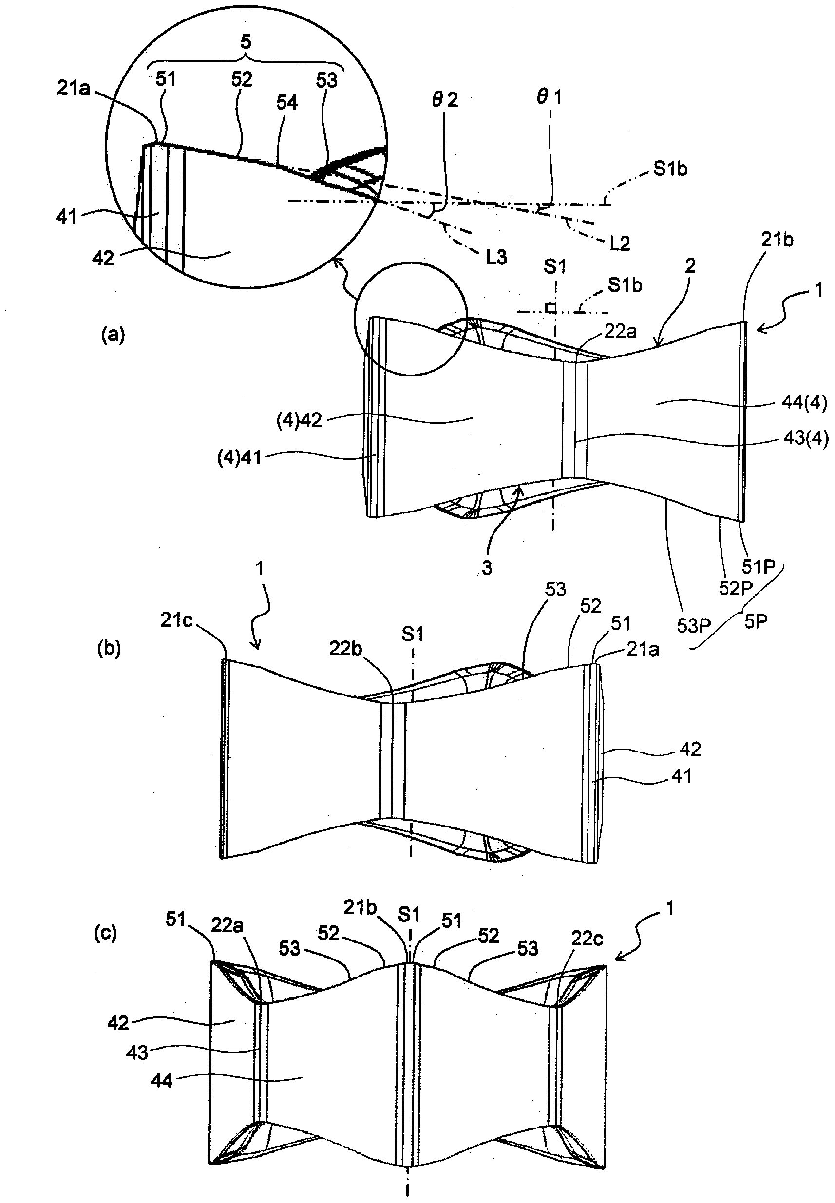
[0025] Hereinafter, regarding the cutting insert according to the first embodiment of the present invention, the insert 1 having a hexagonal shape in a plan view is taken as an example, referring to Figure 1 ~ Figure 4 Explain in detail.

[0026] like figure 1 and figure 2 As shown, the insert 1 of this embodiment generally includes a polygonal (hexagonal) upper surface 2, a lower surface 3 having the same shape as the upper surface 2, side surfaces 4 respectively connected to the upper surface 2 and the lower surface 3, The through hole 6 (installation hole) penetrating from the upper surface 2 to the lower surface 3 , the upper cutting edge 5 located at the intersection of the upper surface 2 and the side surface 4 , and the lower cutting edge 5 located at the intersection of the lower surface 3 and the side surface 4 Cutting edge 5P. For the insert 1, for example, one side of the upper surface 2 may be 5 mm to 100 mm, and the thickness of the upper and lower surfaces ...

no. 2 approach )

[0072] Below, refer to Figure 5 and Image 6 An insert according to a second embodiment of the present invention will be described in detail. In addition, the basic structure of the insert of this embodiment is the same as that of the insert of the said 1st embodiment. Therefore, in the drawings, the same reference numerals are assigned to the same components as those of the insert of the first embodiment, and description thereof will be omitted. Hereinafter, the description will focus on parts having structural differences.

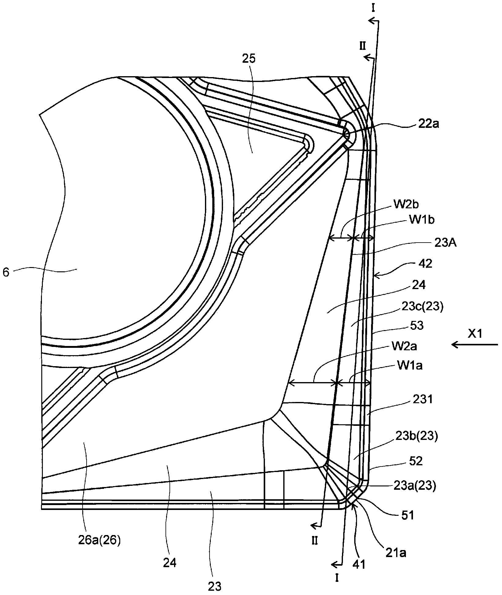
[0073] In the insert 1 of the present embodiment, as Figure 5 and Image 6 As shown, the rake surface 23 has a sub-rake surface 23b and a main rake surface 23c similarly to the first embodiment. The main rake surface 23c is continuous with the main cutting edge 53 and is inclined toward the lower surface 3 by the second rake angle β1 on the basis of the vertical plane S1b as it goes inward. The rake angle β2 is inclined.

[0074] In addition, in ...


PUM


Abstract

The cutting insert according to an embodiment of the present invention is configured in such a manner that an upper cutting edge comprises, in order from a first corner toward a second corner: a corner cutting edge; a secondary cutting edge tilted from the corner cutting edge at a first tilt angle with reference to a perpendicular plane which is perpendicular to the center axis penetrating through the upper and lower faces; and a primary cutting edge tilted from the secondary cutting edge toward the lower face side at a second tilt angle with reference to the perpendicular plane, the second tilt angle being greater than the first tilt angle of the secondary cutting edge. A cross-section of a rake face taken along the direction of the center axis at the end of the rake face which is located on the inner side has a rectilinear or recessed shape in a region bridging at least a secondary rake face and a primary rake face. A cutting tool provided with the cutting insert and a method for manufacturing a cut product using the cutting tool are also provided.

Description

technical field [0001] The present invention relates to a cutting insert, a cutting tool, and a method of manufacturing a cut workpiece using the cutting tool. Background technique [0002] Conventionally, as a cutting insert (hereinafter sometimes referred to as an “insert”) used for face milling, an insert having a structure in which the main cutting edges 24 and 25 are inclined downward through a step has been proposed ( For example, refer to Japanese Patent Application Laid-Open No. 11-333616). [0003] However, in the insert in Japanese Patent Application Laid-Open No. 11-333616, such Figure 7 etc., the rake surfaces 35, 36 at positions corresponding to the main cutting edges 24, 25 are planar surfaces, therefore, the chips generated by the main cutting edges 24, 25 move along the main cutting edges 24, 25 The chips are discharged through the planar rake surfaces 35 and 36 in a state of an inclined shape, so the chips are stable and hard to curl, which may result in l...

Claims


Application Information

Patent Timeline
Patent Type & Authority Applications(China)
IPC IPC(8): B23C5/20B23B27/14B23C5/06
CPCB23C5/207B23C5/06B23C5/205B23C2210/045B23C2200/0411B23C2200/286B23B27/143Y10T407/235Y10T409/303808Y10T407/2268Y10T407/23B23C5/202B23C2200/085B23C2200/203
Inventor 古贺健一郎
Owner KYOCERA CORP
Why Eureka
Try Eureka