drive unit for vehicle

A driving device and vehicle technology, applied in the direction of power device, electric power device, air pressure power device, etc., can solve the problems of unrecorded configuration, insufficient oil heat dissipation, etc.

Active Publication Date: 2016-11-02
HONDA MOTOR CO LTD
View PDF7 Cites 0 Cited by
  • Summary
  • Abstract
  • Description
  • Claims
  • Application Information

AI Technical Summary

Problems solved by technology

[0008] However, in the electric vehicle described in Patent Document 1, since the oil from the mechanical hydraulic pump is directly supplied to the oil passage in the drive shaft, the heat dissipation of the oil is insufficient, and countermeasures such as installing an oil cooler separately are required.
In addition, the electric hydraulic pump does not describe the specific arrangement, and the oil cooled by the cooler is supplied to the travel motor.
In addition, the pump chamber of the mechanical hydraulic pump is composed of the partition wall of the casing and the pump cover, so there is still room for improvement in the assembly workability of the pump.

Method used


Image

  • drive unit for vehicle
  • drive unit for vehicle
  • drive unit for vehicle

Examples


Embodiment Construction

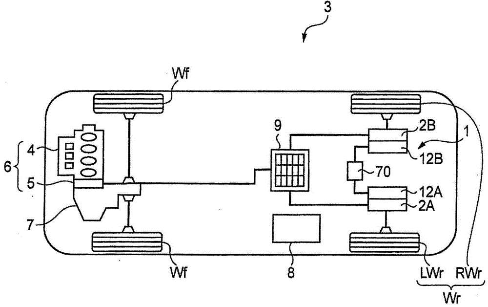
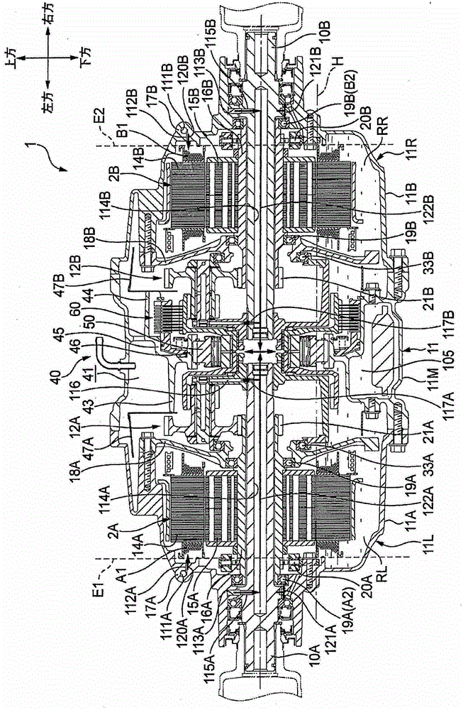
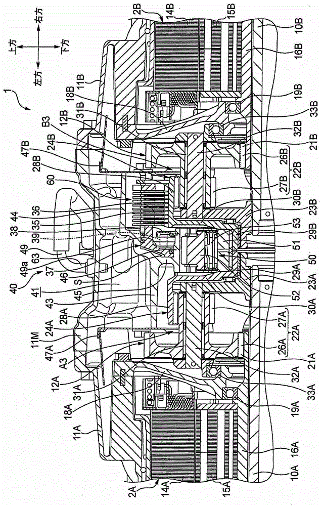
[0146] The driving device for a vehicle of the present invention is a device in which an electric motor is used as a driving source for wheel driving, for example, in figure 1 used in vehicles with a drive system as shown. In the following description, a case where the vehicle driving device is used for driving the rear wheels will be described as an example, but it may also be used for driving the front wheels.

[0147] figure 1 The vehicle 3 shown is a hybrid vehicle having a driving device 6 (hereinafter referred to as a front-wheel drive device) in which an internal combustion engine 4 and an electric motor 5 are connected in series at the front of the vehicle. 7 is transmitted to the front wheel Wf, and on the other hand, the power of the drive device 1 (hereinafter referred to as the rear wheel drive device) provided at the rear of the vehicle separately from the front wheel drive device 6 is sent to the rear wheels Wr (RWr, LWr )transfer. Electric motor 5 of front wh...


PUM


Abstract

The first electric motor cooling flow path (120A) and the first electric motor lubricating flow path (121A) flow from the electric hydraulic pump (70) to the first electric motor (2A) via a position outside one end (E1) of the first electric motor (2A). Oil is supplied to the cooled lubricating parts (A1, A2) of (2A). Further, the second motor cooling flow path (120B) and the second motor lubricating flow path (121B) extend from the electric hydraulic pump (70) to the outside through the other end (E2) of the second electric motor (2B). Oil is supplied to cooled lubricating parts (B1, B2) of the second electric motor (2B).

Description

technical field [0001] The present invention relates to a vehicle drive device, and more specifically, to a vehicle drive device that performs at least one of cooling, lubrication, and cooling and lubrication of an electric motor. Background technique [0002] As a conventional vehicle driving device, the electric vehicle described in Patent Document 1 discloses a vehicle driving device including a pair of electric motors on the left and right, and a mechanical hydraulic pump between the electric motors, Oil is supplied to the oil passage in the drive shaft to lubricate the torque transmission system, and a separately installed electric hydraulic pump cools the travel motor. In this mechanical hydraulic pump, a pump chamber for accommodating a rotating body is constituted by a partition wall of a casing and a pump cover, and is rotated by driving an electric motor. [0003] prior art literature [0004] patent documents [0005] Patent Document 1: Japanese Patent Applicat...

Claims


Application Information

Patent Timeline
Patent Type & Authority Patents(China)
IPC IPC(8): H02K9/19H02K7/00B60K6/448B60K6/48B60K6/52B60K7/00B60K17/02B60K17/04B60L11/14B60L50/16
CPCH02K7/006H02K9/19B60Y2306/03B60K7/0007B60K17/02B60K17/046B62D21/11B60K2001/006B60K2007/0046B60K2007/0092B60K6/448B60K6/48B60K6/52B60Y2306/05B60L50/16B60Y2400/427Y02T10/62Y02T10/64Y02T10/72Y02T10/7072B60K17/06B60W10/30B60W20/00H02K5/203B60K11/02Y02T10/70B60K20/00
Inventor 星野谷武大礒桂一
Owner HONDA MOTOR CO LTD
Why Eureka
Try Eureka