Blast furnace shell air opening flange hole forming method

A tuyere flange and furnace shell tuyere technology is applied in the field of blast furnace shell construction and can solve problems such as poor opening quality

Inactive Publication Date: 2014-03-12
BEIJING SHOUGANG CONSTR GROUP
View PDF4 Cites 2 Cited by
  • Summary
  • Abstract
  • Description
  • Claims
  • Application Information

AI Technical Summary

Problems solved by technology

It is usually opened manually after on-site installation, and the quality of the opening is poor

Method used


Image

  • Blast furnace shell air opening flange hole forming method
  • Blast furnace shell air opening flange hole forming method
  • Blast furnace shell air opening flange hole forming method

Examples


Embodiment Construction

[0023] The specific embodiment of the present invention adopts following steps construction:

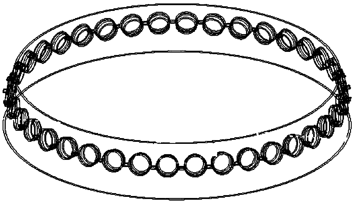
[0024] 1. The center line of the blast furnace shell tuyere flange hole is not perpendicular to the furnace shell plate surface, and is horizontal to the ground ( figure 1 ).

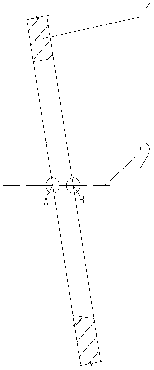
[0025] 2. The flange holes of the tuyere are opened after the steel plate is rolled, and when the flanges of the tuyere are pre-assembled, the center of each tuyere flange is marked with a total station. First, punch the inner center point A on the inner wall of the furnace shell plate 1, and then lead the point A to the outer point B of the furnace shell plate 1. The AB line is the center line of the tuyere flange hole 2 of the tuyere flange opening ( figure 2 ).

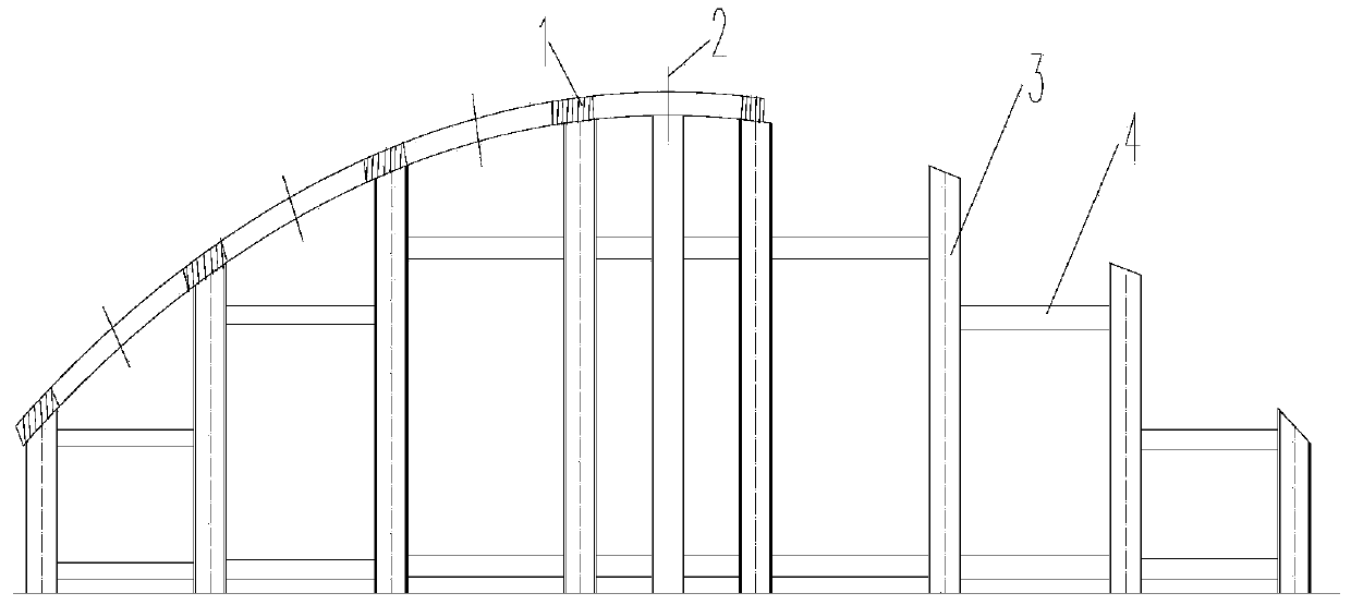
[0026] 3. Design of perforated mold

[0027] The mold is designed according to the angle of the furnace shell plate 2 to ensure that the center line 2 of the flange hole of the tuyere is perpendicular to the ground ( image 3 , Figure 4 ). ...


PUM


Abstract

The invention discloses a blast furnace shell air opening flange hole forming method, and belongs to the technical field of blast furnace shell construction. The processing steps include air opening flange hole positioning, perforating die design and air opening flange hole forming, namely, firstly, a furnace shell plate is fixed to a perforating die, and the air opening flange hole is formed on a cutting bracket through a semi-automatic flame cutter or formed in a manual mode with the center line of the air opening flange hole as the center; secondly, in the perforating process, a point B serves as a perforating center control point, the maximum outer diameter of an air opening flange serves as the diameter, and cutting is carried out according to the included angle between a perforating cutting gun and the ground and the taper of the air opening flange; thirdly, the air opening flange is checked. The blast furnace shell air opening flange hole forming method has the advantages of forming the blast furnace air opening flange hole in a non-perpendicular tapered furnace shell plate surface in a factory and playing a role in guiding cutting of holes similar to large-diameter holes.

Description

technical field [0001] The invention belongs to the technical field of blast furnace shell construction, and in particular provides a blast furnace shell tuyere flange hole opening method, which is suitable for opening the blast furnace shell tuyere flange hole. Background technique [0002] The blast furnace tuyere flange band is usually a tapered band with a certain angle to the ground. The diameter of the tuyere flange hole on the tuyere flange band is relatively large, and the center line of the tuyere flange hole is not perpendicular to the furnace shell plate, but is horizontal to the ground, and the tuyere flange is arranged horizontally. It is usually opened manually after on-site installation, and the quality of the opening is poor. In order to solve the above problems, our company has developed a blast furnace shell tuyere flange hole opening method to realize the opening of blast furnace tuyere flange holes on the non-vertical conical furnace shell plate surface ...

Claims


Application Information

Patent Timeline
Patent Type & Authority Applications(China)
IPC IPC(8): B23K7/10B23K37/04B23K7/00
CPCB23K7/005B23K7/008
Inventor 战学文刘永东阮新伟王克文郭中华
Owner BEIJING SHOUGANG CONSTR GROUP
Why Eureka
Try Eureka