Seismic energy dissipation structure of multi-column bridge piers

A bridge pier and earthquake technology, applied in the field of multi-column bridge pier seismic energy dissipation structures, can solve the problems of high cost of lead-core bearings, difficult repair of connecting beams, and difficulty in immediate repair, etc., and achieves good shock absorption effect, wide application range, The effect of convenient construction

Active Publication Date: 2016-05-11
CHINA RAILWAY ERYUAN ENG GRP CO LTD
View PDF3 Cites 0 Cited by
  • Summary
  • Abstract
  • Description
  • Claims
  • Application Information

AI Technical Summary

Problems solved by technology

However, the cost of lead core bearings is high, and it has not been widely used since its inception. Although the ductile design method can avoid bridge collapse, the permanent deformation of the plastic hinges will cause serious damage to the bridge piers, making it difficult to repair immediately after the earthquake, thus losing the post-disaster bridge. much-needed transport function
[0003] Following the idea of ​​ductility design, the method of using the connecting beam device for shock absorption is also applied, but the connection between the two thin-walled piers will fail after the connecting beam enters the plasticity, and the stability of the bridge pier cannot be guaranteed. more severely damaged, even collapsed
At the same time, the damaged coupling beams are difficult to repair, even if they can be repaired, the economic cost and time cost are very high

Method used


Image

  • Seismic energy dissipation structure of multi-column bridge piers
  • Seismic energy dissipation structure of multi-column bridge piers
  • Seismic energy dissipation structure of multi-column bridge piers

Examples


Embodiment Construction

[0014] The present invention will be further described below in conjunction with the drawings and embodiments.

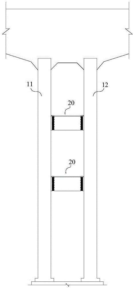
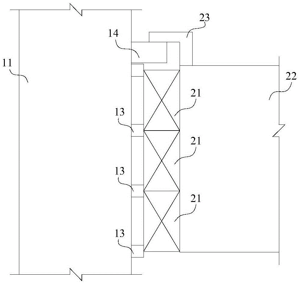
[0015] Reference figure 1 The multi-column pier seismic energy dissipation structure of the present invention includes adjacent left pier columns 11 and right pier columns 12. One or a plurality of energy dissipating cross beams 20 are arranged between the left pier column 11 and the right pier column 12 at intervals along the longitudinal direction. The energy dissipating cross beam 20 includes a steel structure cross beam 22 and is fixedly arranged in its longitudinal direction. The mild steel energy dissipation components at both ends are connected with the left pier column 11 and the right pier column 12.

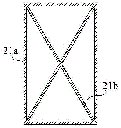
[0016] Reference image 3 with Figure 4 The mild steel energy dissipating component is composed of mild steel energy dissipating unit groups arranged on the end surface of the steel structure cross beam 22 at intervals, and each mild steel energy dissipating uni...


PUM


Abstract

The invention provides an earthquake energy dissipation structure of a multi-pillar pier. The earthquake energy dissipation structure of the multi-pillar pier aims to improve the vibration reducing performance of a bridge so that the bridge keeps the structural integrity after an earthquake. The earthquake energy dissipation structure of the multi-pillar pier comprises a left side pier pillar (11) and a right side pier pillar (12) which are adjacent to each other, wherein an energy dissipation cross tie beam (20) is arranged between the left side pier pillar (11) and the right side pier pillar (12) or a plurality of energy dissipation cross tie beams (20) are longitudinally arranged at intervals between the left side pier pillar (11) and the right side pier pillar (12); the energy dissipation cross tie beam (20) comprises a steel structure cross beam (22), and soft steel energy dissipation members which are fixedly arranged at the two longitudinal ends of the steel structure cross beam (22); the soft steel energy dissipation members are connected with the left side pier pillar (11) and the right side pier pillar (12).

Description

Technical field [0001] The invention relates to a bridge damping structure, in particular to a multi-pillar bridge pier seismic energy dissipation structure. Background technique [0002] Summarizing the development history of structural anti-seismic technology, it can be divided into three methods: "resistance", "elimination" and "isolation". The so-called "resistance" refers to the development of high-performance structural materials and high-performance structural components, such as high-strength concrete, high-strength steel bars, high-strength steel, steel section concrete structures, and concrete-filled steel tube structures, starting from improving the seismic performance of the structure itself. The so-called "dissipation" refers to the use of structural anti-seismic control ideas, adding energy dissipation elements to the structure to help the structure consume seismic energy. Energy dissipation elements such as metal dampers, friction dampers, viscoelastic dampers, vis...

Claims


Application Information

Patent Timeline
Patent Type & Authority Patents(China)
IPC IPC(8): E01D19/00E01D19/04
Inventor 曾永平刘鹏杨平陈克坚袁明杨国静
Owner CHINA RAILWAY ERYUAN ENG GRP CO LTD
Why Eureka
Try Eureka